Matlab implementation
========================
1. Overall Introduction
========================
1.1 Hardware Platform
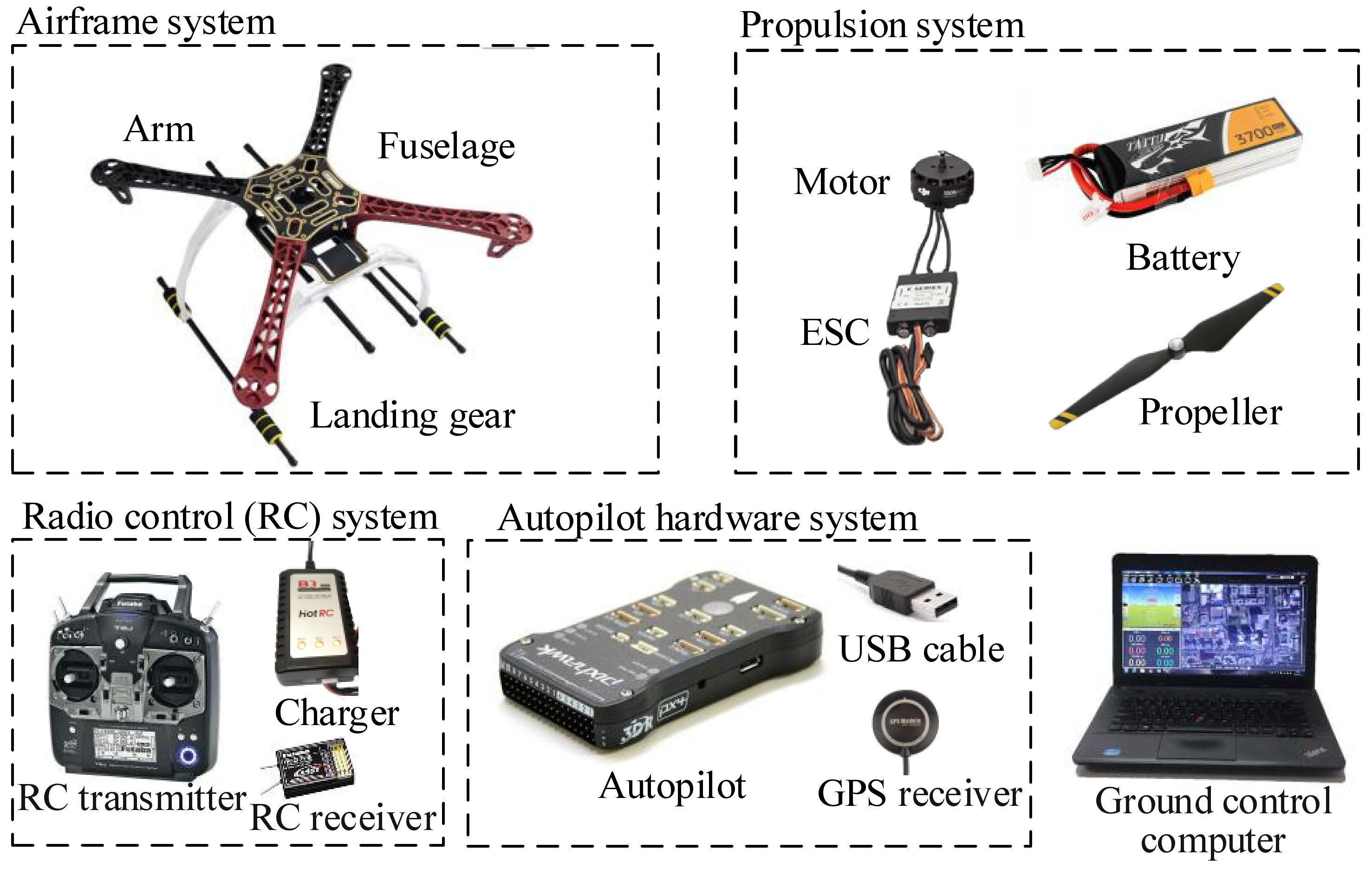
Because all control algorithms are eventually deployed in a real aerial vehicle to perform flight tests, a hardware platform must be prepared for the basic flight test requirements. As shown in Fig. 2.1, the experimental hardware platform recommended in this book is composed of five main parts.
 .. figure:: /images/Quan-ch2-Fig2.1.jpg
:align: center
.. figure:: /images/Quan-ch2-Fig2.1.jpg
:align: center
Fig. 2.1 Composition of experimental hardware platform
(1) Ground computer : it is a high-performance Personal Computer (PC) with an operating system that performs two main tasks.
1) Providing the software operating environment for the simulation software tools to perform functions such as control algorithm development, SIL simulation, automatic code generation, and HIL simulation;
2) Working as a ground control station in outdoor flight tests to achieve functions such as sensor calibration, parameter tuning, real-time control, and communication.

To ensure all the software tools run smoothly on the ground computer, the following basic configuration requirements must be satisfied.

* Operating System (OS): Windows 7 ~ 10, 64-bit system
* Processor: Intel I5 series or above
* Memory: 8G or above
* Graphics: discrete graphics, memory 2G or more
* Storage: 30G available space (solid-state drives are recommended)
* Interface: at least one USB Type-A
* Monitor: screen resolution 1080P or above

Noteworthy, for higher development efficiency, computer performance must be as high as possible.
(2) Autopilot system (also called flight control system) : as the operating platform of control algorithms, it has many sensors and powerful computing processor to estimate flight states and calculate the control signals for the propulsion system to realize the flight control of multicopters. For this book, we selected awidely-used open-source autopilot—Pixhawk as the development and experimental autopilot system. Pixhawk is an independent open-hardware project that aims to provide standard readily-available, high-quality, and low-cost autopilot hardware for education, amateurs, and developers. For different flight mission, performance, and cost requirements, the Pixhawk provides a series of autopilot hardware products that highly promote the development of multicopters.
(3) Radio Control (RC) system : it mainly includes an RC transmitter, an RC receiver, and a battery charger. The RC system is used to send control commands from the pilot on the ground to the autopilot system on the multicopter to realize remote flight control.
(4) Propulsion system : it mainly includes a battery pack and several propellers, Electronic Speed Controllers (ESCs), and motors. The propulsion system is used to receive the Pulse Width Modulation (PWM) control signals from the autopilot system, and control the movement of a multicopter with thrust and torque generated by the rotation of propellers and motors.
(5) Airframe system : it includes a fuselage, landing gear, and several arms. The airframe is used to support the propulsion system and the autopilot system and carry a payload; thus, it is required to have excellent aerodynamic performance and structural strength to ensure that flight missions are successfully and reliably accomplished.
1.2 Software Platform
This experimental platform relies on many software tools to realize controller design, code generation, autopilot code compilation, HIL simulation, and other functions. The Simulation Software Package published along with this book has a one-click installation script. Readers can click the script to finish all the installation and configuration process of the required software environment. The MATLAB/Simulink and the Simulation Software Package comprise the software platform, which contains the following.
(1) MATLAB/Simulink : it is a visual simulation tool developed by Mathworks <https://www.mathworks.com/>_ ,
which is widely-used in aerial vehicles, cars, and other applications. It can be
easily applied to develop simulation systems for dynamic system modeling,
controller design, hardware and software simulation, and performance analysis
through a modular programming language. The simulation software package
and source code published along with this book support MATLAB R2017b and
above. The required MATLAB toolboxes include the following.
| required | required |
|---|---|
|
|
below kramdown table code works in Firefox and in Chrome
| Installed | Installed | Installed | |
|---|---|---|---|
|
|
|
|
| kramdown_table |
(2) Pixhawk Support Package (PSP) Toolbox3 <https://ww2.mathworks.cn/hardware-support/forms/pixhawk-downloads-conf.html>_ : it is a Simulink toolbox officially
released by Mathworks for controller design, code generation, and firmware
upload of the Pixhawk autopilot. We have made some updates and optimizations
based on the official PSP toolbox to ensure compatibility with the latest Pixhawk
and MATLAB versions.
(3) FlightGear-Flight Simulator <http://home.flightgear.org/>_ : it is a popular open-source flight simulator
that can be used to easily observe the flight states of a simulated aerial vehicle in
Simulink by receiving flight data from Simulink via a User Datagram Protocol
(UDP) interface.
(4) PX4 Software-source Code <https://github.com/PX4/Firmware>_ : PX4 <https://px4.io>_ is an open-source flight control software
system that runs on the Pixhawk hardware platform. The Pixhawk hardware +
PX4 software constitutes an integrated autopilot system, which is one of the most
widely-used autopilot systems for aerial vehicles.
(5) PX4 Toolchain-Compiling Environment : it is used to compile the PX4 source code along with the controller algorithms generated by the PSP toolbox into a “.px4” format firmware file. Then, the firmware file is uploaded into the Pixhawk autopilot hardware (similar to the process of reinstalling an operating system on a PC). The control algorithm generated by the PSP toolbox will automatically run after Pixhawk restarts.
(6) Eclipse C/C++-Integrated Development Environment (IDE) <https://www.eclipse.org/downloads/packages/>_: it is used to perform the pre-flight tasks (e.g., sensor calibration and parameter tuning) for the Pixhawk autopilot before the multicopter takes off. The QGC is also used to receive the flight states and send the control commands of the multicopter through wireless radio telemetry during flight tests.
(7) QGroundControl (QGC)QGround Control Station <http://qgroundcontrol.com/>_ : it is used to perform the pre-flight tasks (e.g., sensor calibration and parameter tuning) for the Pixhawk autopilot before the multicopter takes off. The QGC is also used to receive the flight states and send the control commands of the multicopter through wireless radio telemetry during flight tests.
(8) CopterSim—Real-Time Motion Simulation Software : it is a real-time motion simulation software developed for the Pixhawk/PX4 autopilot system. Readers can configure multicopter models in CopterSim, and connect it to the Pixhawk autopilot via the USB serial port to perform indoor HIL simulations.
(9) **3DDisplay—3D Visual Display Software&& : it is a real-time 3D visual display software. It receives the flight data of CopterSim through UDP to display the attitude and position of a multicopter in real-time. CopterSim and 3DDisplay together constitute an integrated HIL simulation platform. The distributed independent operation mechanism of CopterSim and 3DDisplay provides future compatibility for swarm simulations.
1.3 Relationship Between sw and hw Platforms
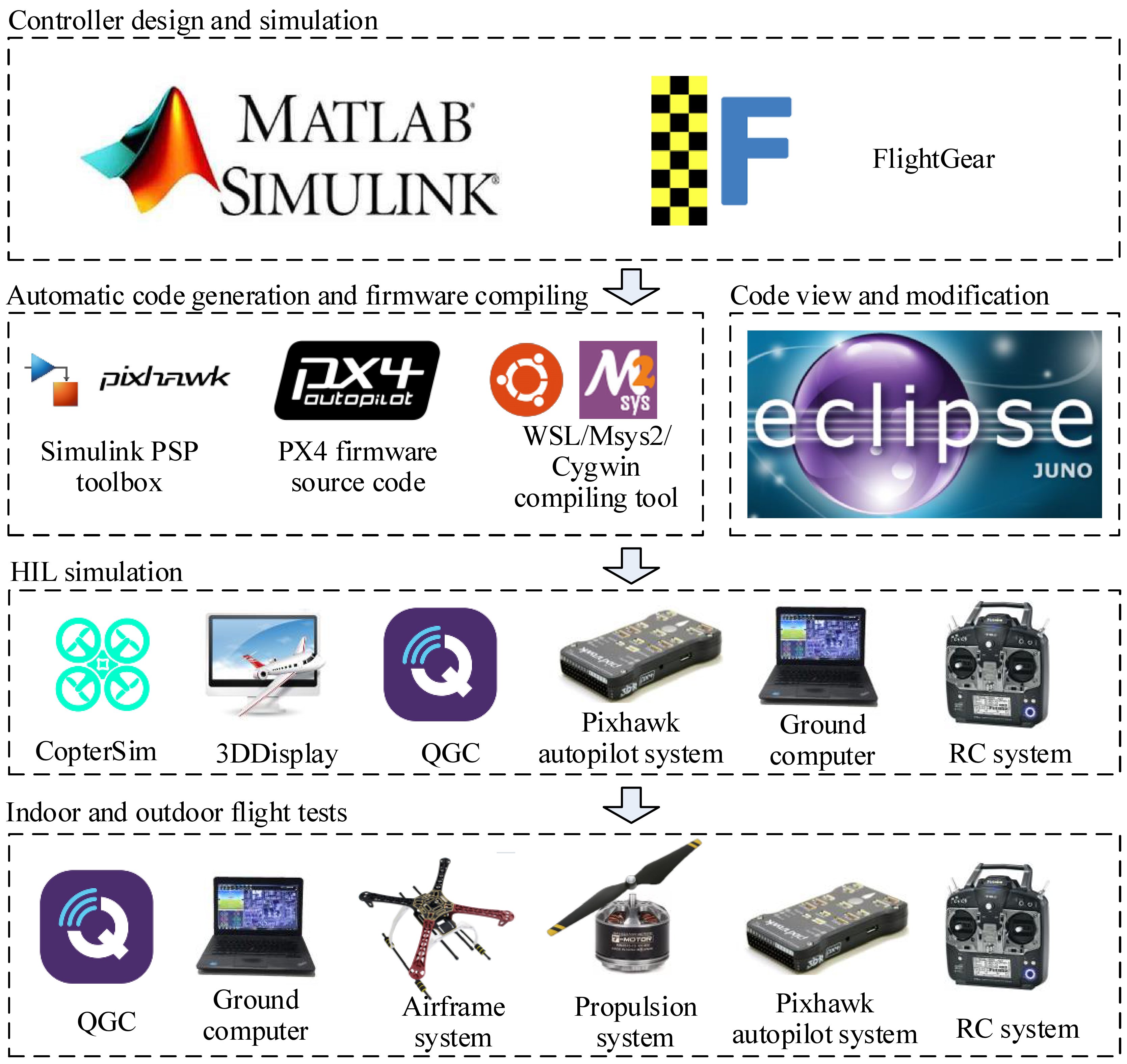
The previous subsection introduced the hardware and software components of the required experimental platform. These components seem to be diverse and complex, but they are necessary for the development and practical flight experiments of multicopters. Familiarization with these tools can reduce the development difficulty and significantly improved efficiency, which can save a lot of time during the learning process. Figure 2.2 shows the relationships among the various hardware and software components and the overall process of the experimental platform. Most of the software tools play important roles in all the phases of multicopter development. The roles and application methods of the components presented in Fig. 2.2 are introduced in detail in the following sections.
 .. figure:: /images/Quan-ch2-Fig2.2.jpg
:align: center
.. figure:: /images/Quan-ch2-Fig2.2.jpg
:align: center
Fig. 2.2 Hardware and software components used in different phases
==============================
2. Software Package Installation
==============================
The installation process of the Simulation Software Package is highly automated and readers can run a one-click installation script to achieve rapid and automatic deployment.
2.1 Installation Steps
The installation steps are summarized below.
(1)Download the installation image file “RFLYExpPspSoftwarePack.iso” of the Simulation Software Package from :doc:Download and Support<../7_DownloadAndSupport/DownloadAndSupport>,
and then unzip it or mount it to a virtual drive folder. download_link
onedrive
use UltraISO to mount the image before following the next step.
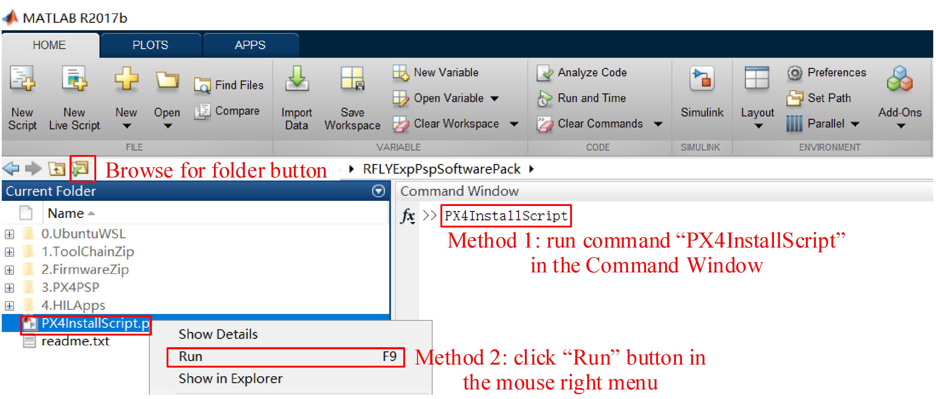
(2) Open MATLAB and click the “Browse for Folder” button (see Fig. 2.3). On the folder selection window, select the folder “RFLYExpPspSoftwarePack” obtained in the previous step.
(3) As shown in Fig. 2.3, tap the command “PX4InstallScript” in the “Command Window” of MATLAB and press the “Enter” key on the keyboard to run the one-key installation script. Note that another convenient way to run the one-key script is to select the “PX4InstallScript.p” file (see Fig. 2.3) with the mouse right key, and click the “Run” button on the pop-up menu.
 .. figure:: /images/Quan-ch2-Fig2.3.jpg
:align: center
.. figure:: /images/Quan-ch2-Fig2.3.jpg
:align: center
Fig. 2.3 Installing multicopter simulation software package with one-click installation script
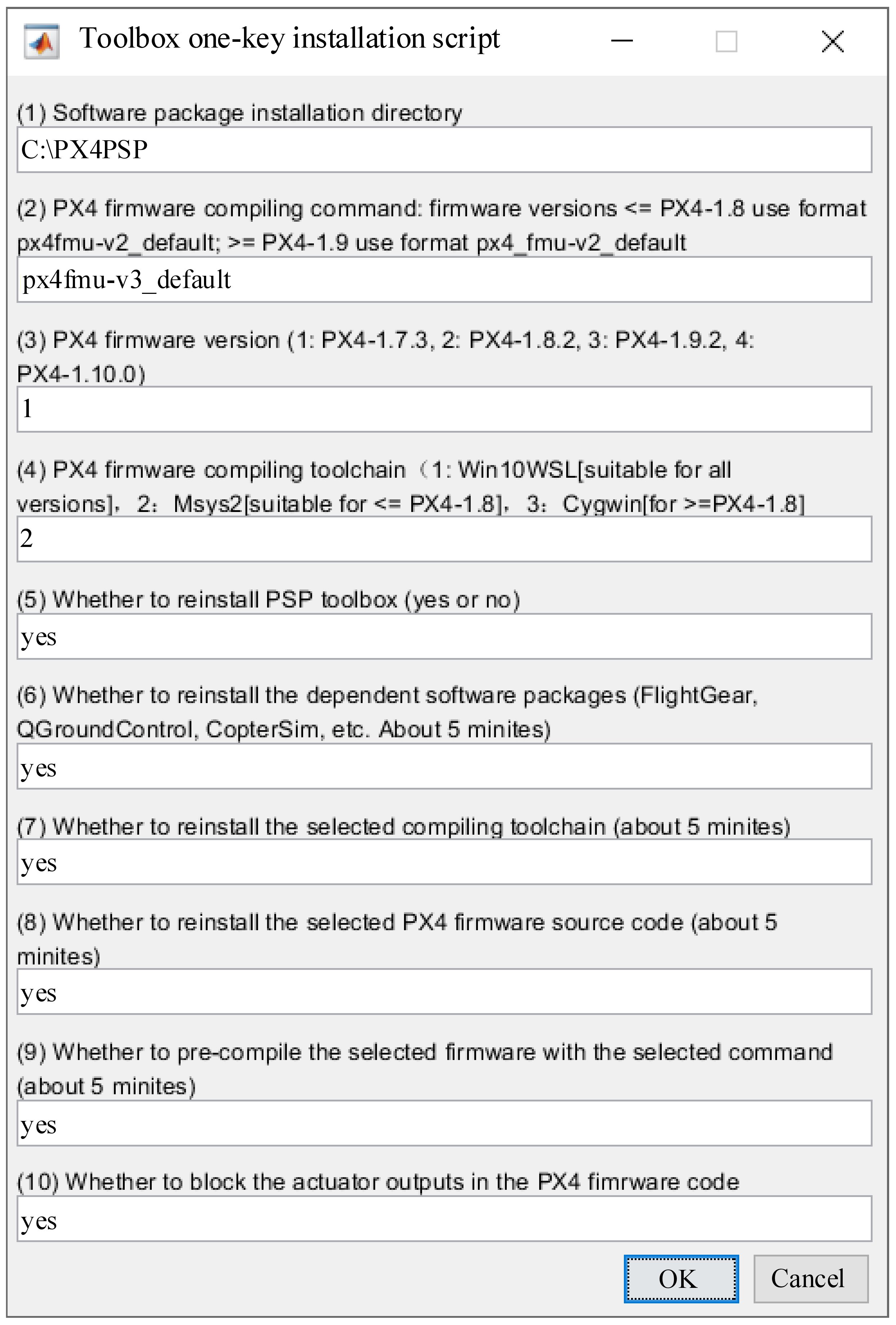
(4) In the pop-up configuration window shown in Fig. 2.4, select the required configuration according to the actual hardware and software requirements (the default configuration is recommended for beginners, where the compiling command is px4fmu-v3_default, the PX4 firmware version is 1.7.3, and the installation directory is the C disk, which may occupy around 6G storage), and click the “OK” button in Fig. 2.4.
you can install to D drive and use vscode workspace for the firmware development
 .. figure:: /images/Quan-ch2-Fig2.4.jpg
:align: center
.. figure:: /images/Quan-ch2-Fig2.4.jpg
:align: center
Fig. 2.4 Options of PX4InstallScript
(5) Wait patiently for the package to be successfully installed and deployed, which may take around 30 min.
Noteworthy :
(1) Antivirus software may prevent this script from generating desktop shortcuts. If the script prompts that the shortcut generation has failed, please close the antivirus software (Windows 10 should also turn off the “Real-time protection” option in the Settings page) and manually click the “GenerateShortcutCMD.bat” script in the installation directory (the default directory is C:PX4PSP) to automatically generate all the software shortcuts.
beaware that the step above would cause forcing new path to set, which would cause some programms needs redoing the system environment variables.
(2) If readers want to change the firmware configurations or restore the compiling environment, just run the “PX4InstallScript” command again and select the required options.
(3) Readers can check the document “readme.txt” in the folder “RFLYExpPspSoftwarePack” for more detailed notes.
2.2 Advanced Settings
For advanced independent developers, Fig. 2.4 provides options to select the installation directory, Pixhawk hardware version, PX4 firmware version, compiling command, compiling environment, etc. The options in Fig. 2.4 are explained in detail below.
(1) Software package installation directory . All dependent files on the software package are installed in this directory, which requires around 6G storage. The default installation directory is “C: PX4PSP”. If the C disk space is not suffi- cient, readers should choose a directory in other disks; the directory name must be correct and only in English to prevent compilation failures.
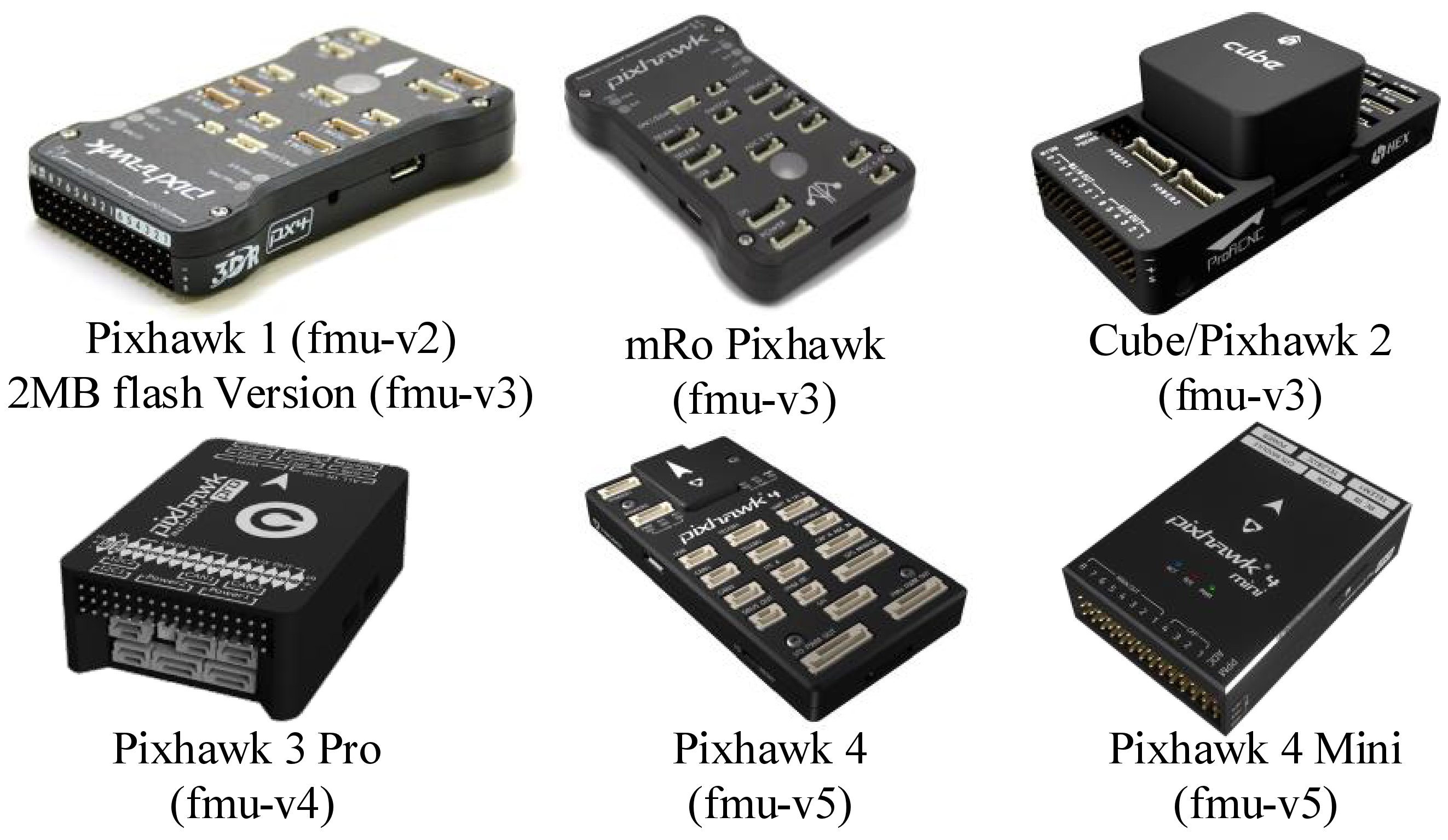
(2) PX4 firmware compiling command . The default compiling command for PX4 is “px4fmu-v3default”. By selecting this compiling command, the compiling toolchain is automatically called to compile the PX4 source code to a firmware file “px4fmu-v3_default.px4” after the PSP generates the controller code. Then, the file “.px4” is uploaded to the supported hardware to realize the deployment of the control algorithms. Different Pixhawk hardware products must select different PX4 firmware compiling commands. Figure 2.5 shows some Pixhawk hardware products, where “px4fmu-v3_default” can be used for three popular products: Pixhawk 1 (2MB flash version), mRo Pixhawk <https://docs.px4.io/master/en/flight_controller/mro_pixhawk.html.>
and Cube (Pixhawk 2 <https://docs.px4.io/master/en/flight_controller/pixhawk-2.html>_ ).
TThe command “px4fmu-v2default” corresponds to the most famous Pixhawk 1 <https://docs.px4.io/master/en/flight_controller/pixhawk.html> .
PX4 also supports other hardware (for example, Intel Aero <https://software.intel.com/en-us/aero/drone-kit>_ ,
Crazy-flie <https://www.bitcraze.io/crazyflie-2/>_ , and so on).
The corresponding compiling commands <http://dev.px4.io/master/en/setup/building_px4.html>_
are listed below.
- Pixhawk 1: px4fmu-v2_default.px4
- Pixhawk 1 (2MB flash version): px4fmu-v3_default.px4
- Pixhawk 4: px4fmu-v5_default
- Pixracer: px4fmu-v4_default
- Pixhawk 3 Pro: px4fmu-v4pro_default
- Pixhawk Mini: px4fmu-v3_default
- Pixhawk 2: px4fmu-v3_default (cube black)
- mRo Pixhawk: px4fmu-v3_default
- HKPilot32: px4fmu-v2_default
- Pixfalcon: px4fmu-v2_default
- Dropix: px4fmu-v2_default
- MindPX/MindRacer: mindpx-v2_default
- mRo X-2.1: auav-x21_default
- Crazyflie 2.0: crazyflie_default
- Intel Aero Ready to Fly Drone: aerofc-v1_default.
 .. figure:: /images/Quan-ch2-Fig2.5.jpg
:align: center
.. figure:: /images/Quan-ch2-Fig2.5.jpg
:align: center
Fig. 2.5 Pixhawk hardware series products with compiling commands
(3) PX4 firmware version . The version of the PX4 source code is updated constantly, and the latest firmware version was 1.10 when this book was written. As the firmware version is upgraded, new features may be introduced, and more new products will be supported, but the compatibility with some old autopilot hardware will be affected. Because the Pixhawk 1 (2MB flash version, or mRo Pixhawk) hardware selected in this book is an old Pixhawk product with LED for better experimental observation effect, the older PX4 firmware version 1.7.3 was selected with the compiling command “px4fmu-v3_default” to achieve better-using effect.
(4) PX4 firmware compiling toolchain . Because the compilation of PX4 source code depends on the Linux compiling environment, the software package provides three sets of compiling toolchains to realize the simulation of the Linux compiling environment under the Windows environment.
1) Win10WSL <https://en.wikipedia.org/wiki/Windows_Subsystem_for_Linux>_ based on the Windows Subsystem compiler environment for Linux (WSL);
2) the Msys2Toolchain based on Msys2 <https://baike.baidu.com/item/MSYS2>_ toolchain;
3) the CygwinToolchain based on the Cygwin <https://www.cygwin.com/>_ toolchain.
(5) Whether to reinstall the PSP Toolbox (yes or no) . If this option is set to “yes”, the PSP Toolbox is installed on MATLAB/Simulink. If the PSP toolbox has already been installed, a new installation of the PSP Toolbox is performed. If this option is set to “no”, the script does not do anything on the existing PSP toolbox (it will not uninstall the PSP toolbox or carry out other actions).
(6) Whether to reinstall the dependent software packages . If this option is set to “yes”, software tools (such as FlightGear, QGC, CopterSim, and 3DDisplay) are deployed to the selected installation directory and shortcuts for them are generated on the desktop. The related drivers for Pixhawk hardware are also installed. If the software tools have already been installed, selecting “yes” will remove the old installation files and reinstall them. If this option is set to “no”, then no change will be made.
(7) Whether to reinstall the selected compiling toolchain . If this option is set to “yes”, the selected compmap CH5 to a thrde.
(8) Whether to reinstall the selected PX4 firmware source code . If this option is set to “yes”, the selected PX4 firmware source code will be deployed to the selected installation directory. If the firmware files already exist, the old firmware folder will be deleted, and a new copy of the source code will be deployed. If this option is set to “no”, then no change will be made.
(9) Whether to pre-compile the selected firmware . If this option is set to “yes”, the PX4 source code will be pre-compiled. This can greatly save the compiling time of the subsequent code generation process; whether the compiling environment is installed properly can also be checked. If this option is set to “no”, then no change will be made.
(10) Whether to block the actuator outputs of the PX4 original controller . If this option is set to “yes”, the control signals of the PX4 original controller will be blocked to prevent them from conflicting with the generated controller in Simulink. This option must be set to “yes” for the simulations and experiments in this book. If this option is set to “no”, the PX4 outputs will not be blocked, and this mode can be used to test the PX4 original controller.
.. note::
2.3 Installation Completion
When the above one-key installation scripted is successfully executed, readers can check the installed content with the following procedure.
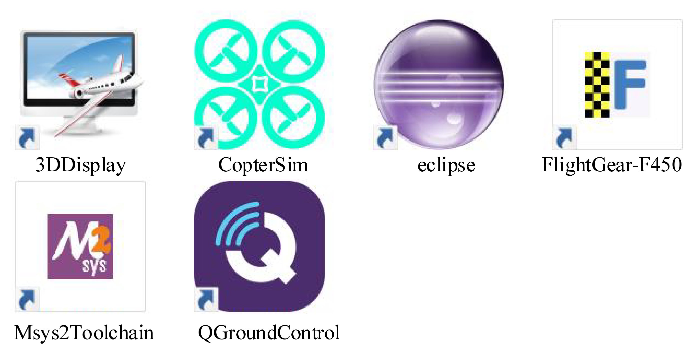
(1) As shown in Fig. 2.6, the shortcuts for the core software tools will be generated on the desktop.
 .. figure:: /images/Quan-ch2-Fig2.6.jpg
:align: center
.. figure:: /images/Quan-ch2-Fig2.6.jpg
:align: center
Fig. 2.6 Desktop shortcuts of simulation software package
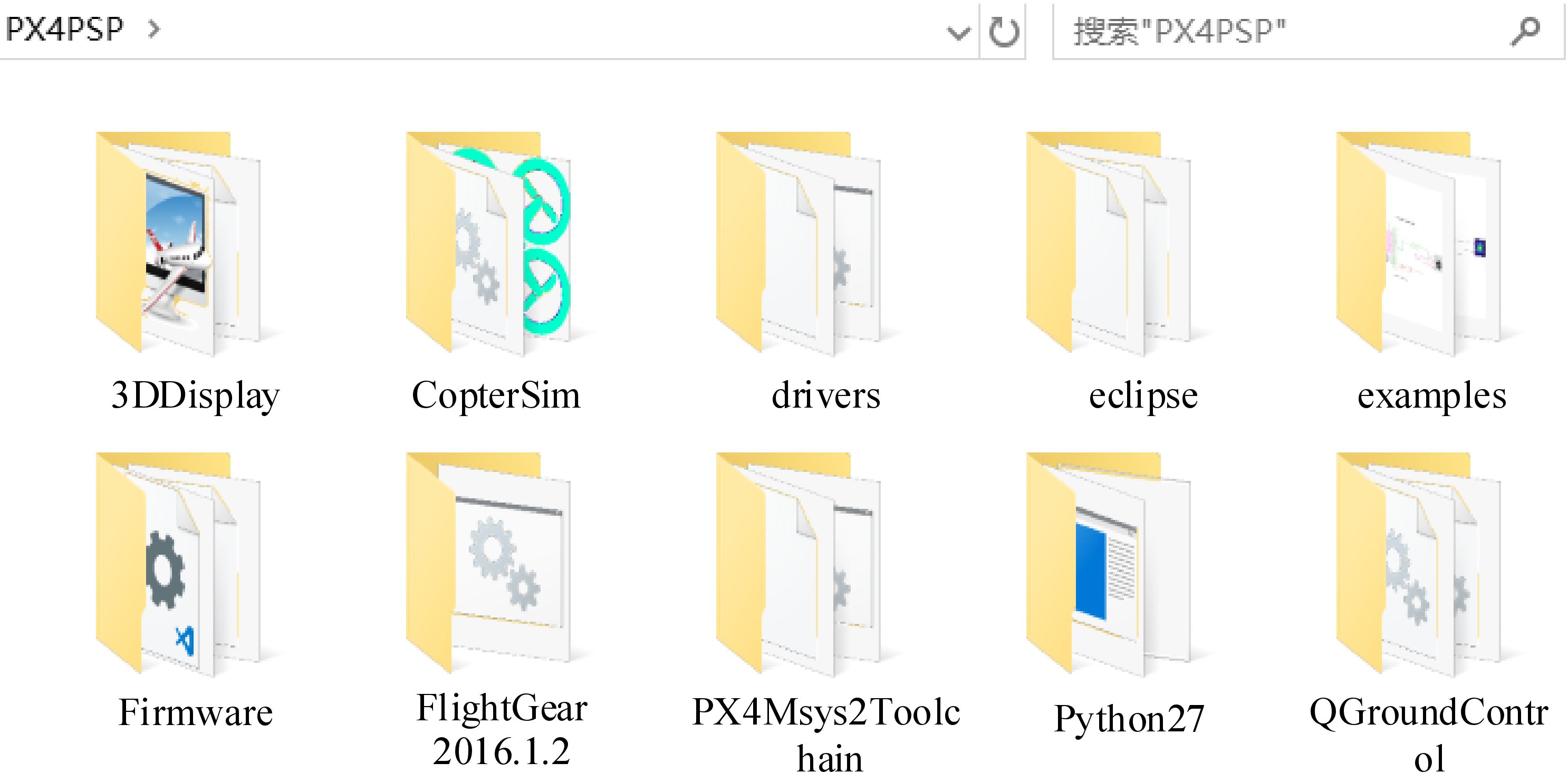
(2) As shown in Fig. 2.7, the folders of all software tools are stored in the selected installation directory (the default is “C:PX4PSP”). Note that all the software tools are completely portable and independent of the original software (e.g., official versions of QGC and FlightGear) on Windows. In Fig. 2.7, the folder “Firmware” stores the PX4 source code. The folder “examples” stores Simulink source code examples of the PSP toolbox; the folder “drivers” stores Pixhawk drivers. The folder “Python27” stores a Python environment for the automatic firmware uploading of the PSP toolbox. The names of other folders are the same as the software names, whose detailed introduction can be found in Sect. 2.1.2.
 .. figure:: /images/Quan-ch2-Fig2.7.jpg
:align: center
.. figure:: /images/Quan-ch2-Fig2.7.jpg
:align: center
Fig. 2.7 All files in installation directory of simulation software package
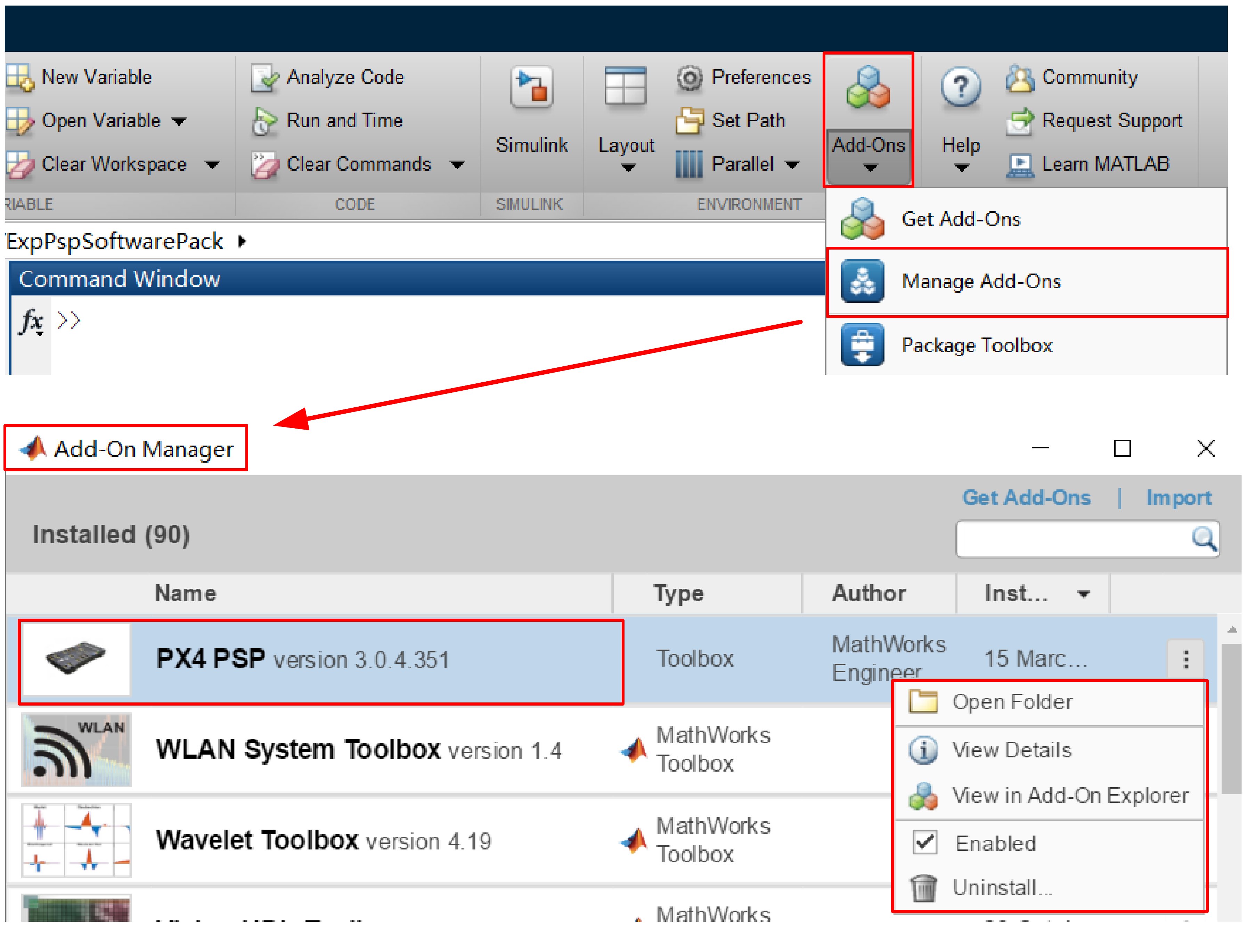
(3) As shown in Fig. 2.8, the installed PSP toolbox can be found on the “Add-Ons” - “Manage Add-Ons” page of MATLAB. On this page, some management operations can be performed for the PSP toolbox that includes disabling, uninstalling, and viewing the installation directory. Note that the PSP toolbox can be installed once for all the MATLAB applications on a computer whose versions are higher than or equal to MATLAB R2017b. than or equal to MATLAB R2017b.
Due to matlab menu being syntax-based, you will have to open a xls file first, before you see the libraryBrowser
 |
 |
| I’ve wasted time figuring this out |
 .. figure:: /images/Quan-ch2-Fig2.8.jpg
:align: center
.. figure:: /images/Quan-ch2-Fig2.8.jpg
:align: center
Fig. 2.8 PSP Toolbox management page in MATLAB
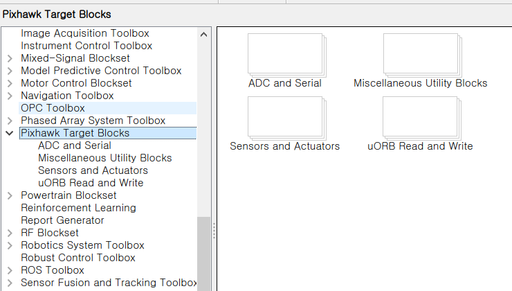
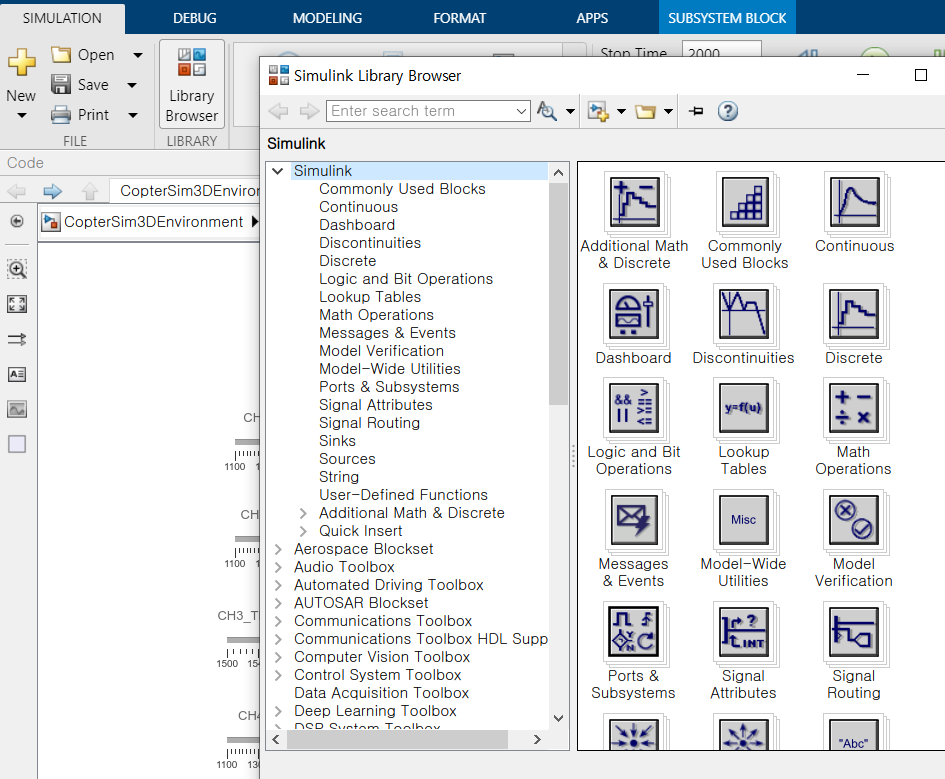
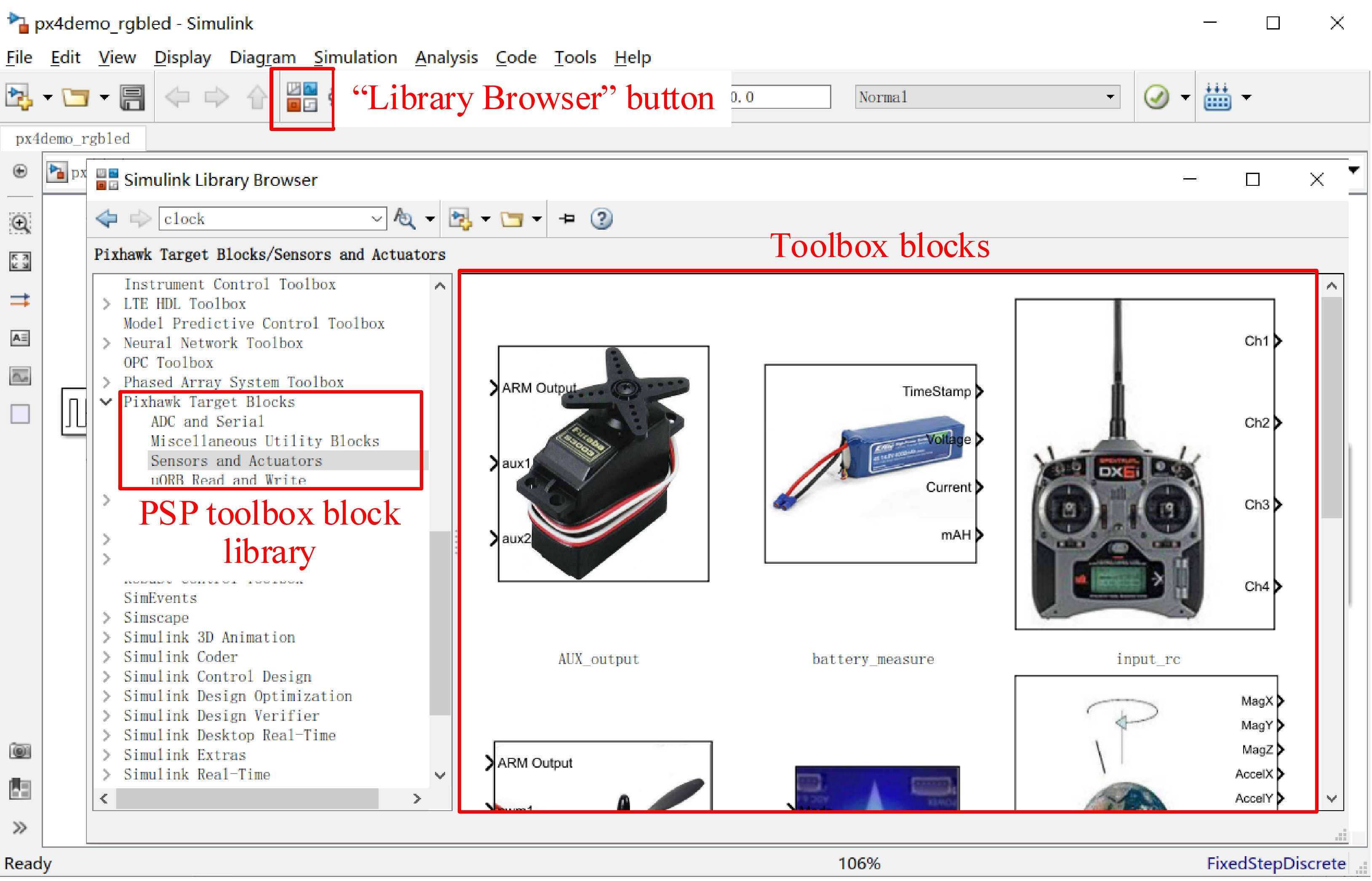
(4) As shown in Fig. 2.9, readers can open any Simulink file and click the “Simulink Library Brower” button to open the Simulink library browser, and then find the “Pixhawk Target Blocks” library generated by the PSP toolbox.
 .. figure:: /images/Quan-ch2-Fig2.9.jpg
:align: center
.. figure:: /images/Quan-ch2-Fig2.9.jpg
:align: center
Fig. 2.9 PSP toolbox in Simulink library browser
If readers want to uninstall the simulation software package, they can carry out the following steps:
(1) Delete all the desktop shortcuts presented in Fig. 2.6; (2) Delete all files and folders in the installation directory presented in Fig. 2.7; (3) In the “Management Additional Functions” page of MATLAB presented in Fig. 2.8, click the “Uninstall” button to uninstall the PSP toolbox.
2.4 Brief Introduction to Software
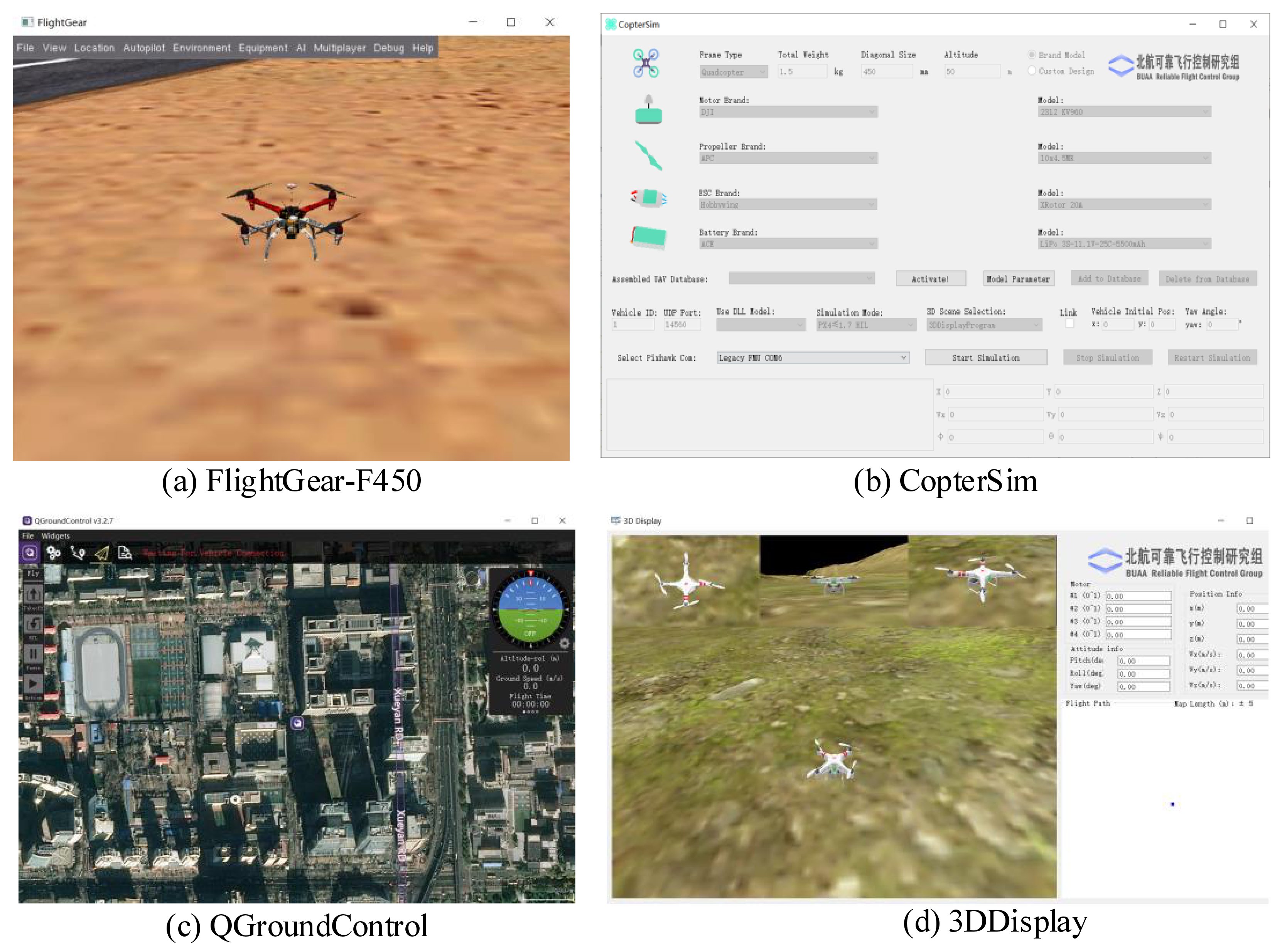
(1) Double-click the desktop shortcuts shown in Fig. 2.6, which include “FlightGearF450”, “CopterSim”, “QGroundControl” and “3DDisplay”. Then, check the software User Interface (UI) one by one with Fig. 2.10 to confirm that each software can operate correctly.
 .. figure:: /images/Quan-ch2-Fig2.10.jpg
:align: center
.. figure:: /images/Quan-ch2-Fig2.10.jpg
:align: center
Fig. 2.10 Basic software UIs for simulation tools
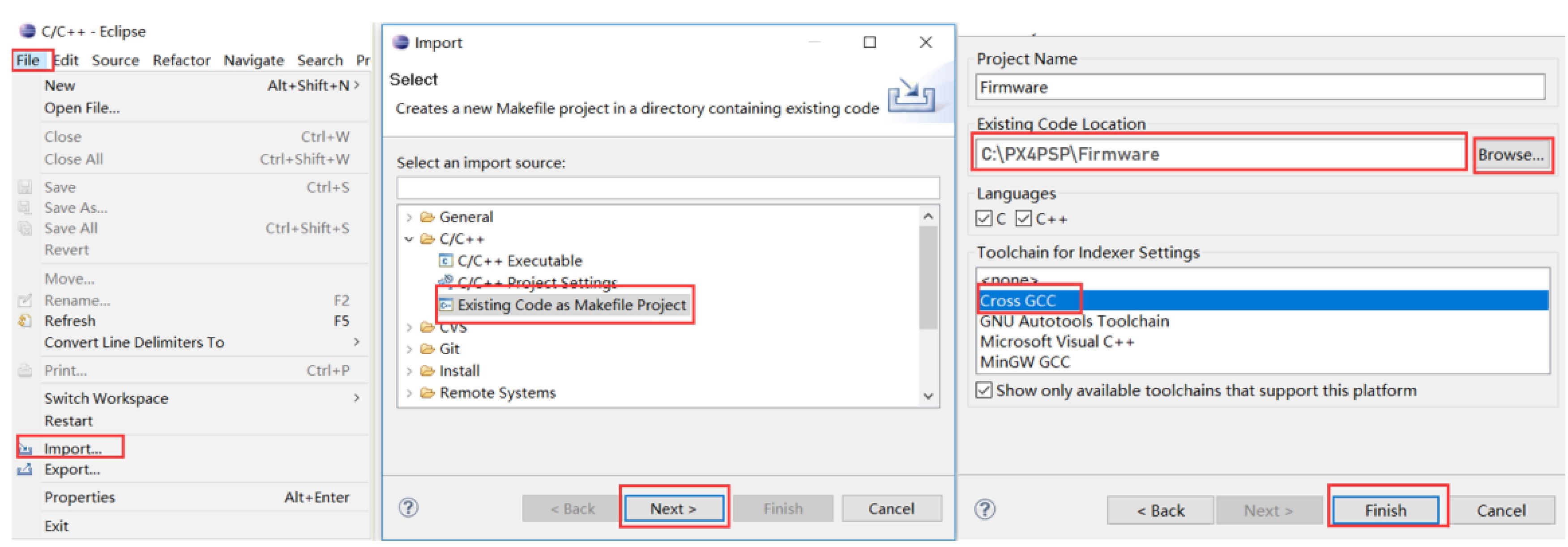
(2) Double-click the desktop shortcut “Eclipse” in Fig. 2.6 to open the Eclipse software. As shown in Fig. 2.11, click “File” – “Import…” – “C/C++”—“Existing Code as Makefile Project” from the menu bar of the Eclipse, and then click “Next”. In the “Existing Code Location” section of the pop-up window, click the “Browse” button to locate the “Firmware” folder in the installation directory (default is “C:PX4PSP”), then choose “Cross GCC” and click the “Finish” button.
 .. figure:: /images/Quan-ch2-Fig2.11.jpg
:align: center
.. figure:: /images/Quan-ch2-Fig2.11.jpg
:align: center
Fig. 2.11 Importing PX4 Firmware source code into Eclipse
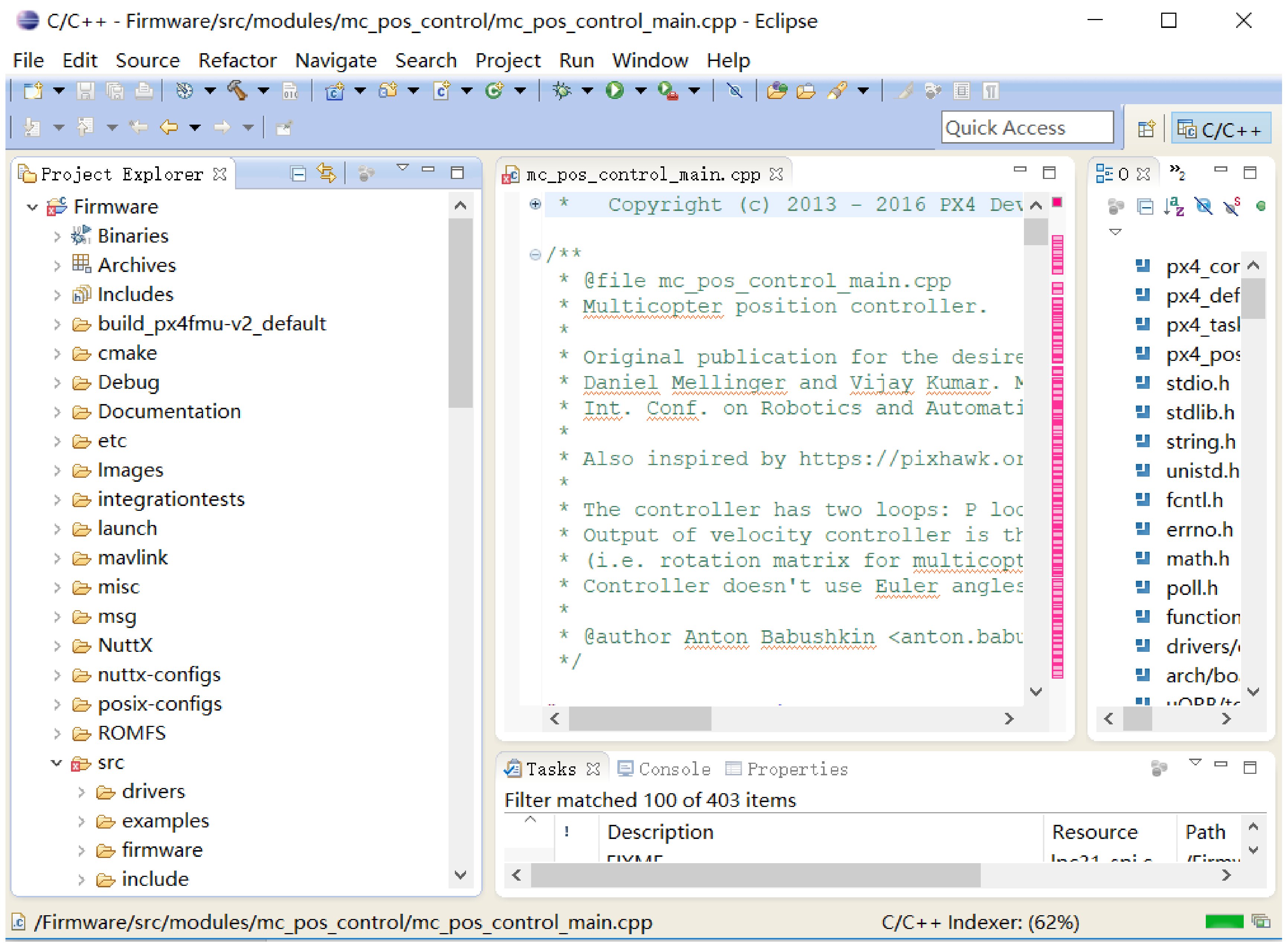
After completing the above steps, as shown in Fig. 2.12, the source code and directory structure of the “Firmware” can be found in the “Project Explorer” window, where readers can read the PX4 source code and try to modify it. Readers can also view the PX4 developer documentation website to clearly understand the architecture and implementation principles of the PX4 algorithms and deepen the understanding of an actual flight control system. Note that: a “Welcome” tab will cover the content shown in Fig. 2.12 when readers first open Eclipse, it must be closed manually.
 .. figure:: /images/Quan-ch2-Fig2.12.jpg
:align: center
.. figure:: /images/Quan-ch2-Fig2.12.jpg
:align: center
Fig. 2.12 Eclipse code reading interface
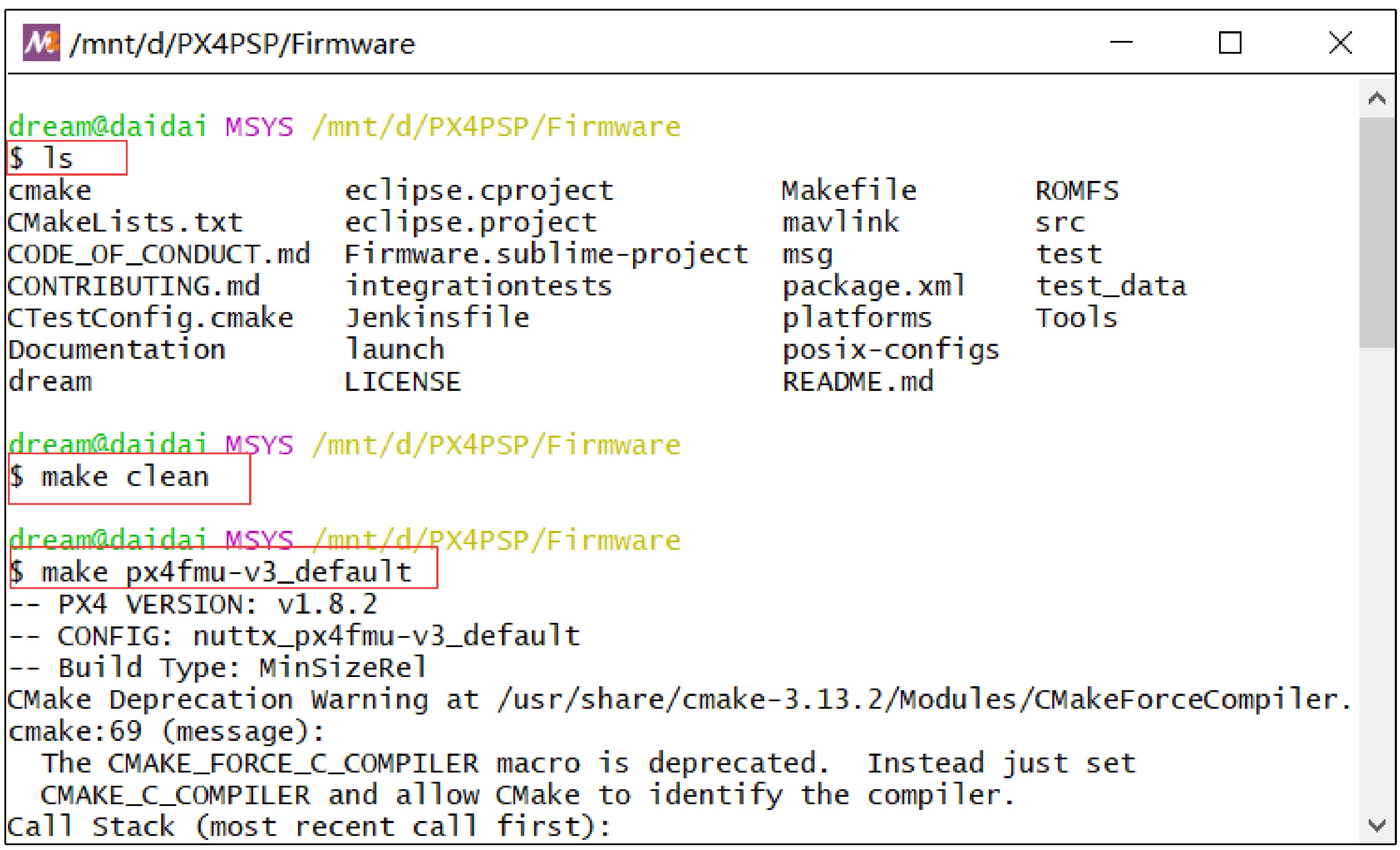
(3) Double-click one of the three shortcuts “Win10WSL”, “Msys2Toolchain” or “CygwinToolchain” on the desktop to pop up the command window interface shown in Fig. 2.13 (the original UI has a pure black background, and the image color has been reversed for reading). Because the compiling toolchains are essentially Linux emulation software, the basic Linux commands (such as “ls”, “pwd”, and “gcc—version”) can be tapped on the command line. For readers who are unfamiliar with Linux operations, this compiling toolchain can also be used as a Linux learning and practice tool. The most important function of this toolchain is to compile the source code of PX4 and generate the “.px4” firmware file. As shown in Fig. 2.13, “make clean” can be tapped on the command line to clear the old compiling files, and the “make px4fmu-v3_default” command is used to compile the source code to the firmware file “C:PX4PSPFirmwarebuildpx4fmu-v3_defaultpx4fmu-v3_default.px4” for Pixhawk 1 (2MB flash version). Because the PSP toolbox will automatically call this compiling command after the code is generated, readers do not need to know how to use it.
 .. figure:: /images/Quan-ch2-Fig2.13.jpg
:align: center
.. figure:: /images/Quan-ch2-Fig2.13.jpg
:align: center
Fig. 2.13 Commands tapped in compiling toolchains
================================
3. Hardware Platform Configuration
================================
This chapter will introduce the RC system configuration, Pixhawk autopilot system configuration, airframe, and propulsion system configuration.
3.1. RC System Configuration
There are two RC system products presented in this book, which are RadioLink AT9S and Futaba T14SG. The receivers of these RC systems have the S.BUS output function that can transmit the PWM signals of all channels to the flight control through one data line. Radio Link AT9S is relatively inexpensive, and it is suitable for indoor experiments; Futaba T14SG is relatively expensive, but it offers better performance and reliability, which makes it more suitable for actual outdoor flight tests. RC transmitters with “Left-hand throttle (Mode 2)” configuration are selected in this book, whose left stick is the throttle lever without the auto-return function. RC transmitters with “Right-hand throttle (Mode 1)” and “Left-hand throttle” configurations have different hardware structures that cannot be modified through the software setting page; thus, readers need to pay attention to this. The following subsections detail the configuration steps of the two RC systems. Other RC systems can be configured in a similar way.
3.1.1. RadioLink AT9S Configuration Method RadioLink AT9S includes an RC transmitter and an R9DS RC receiver. Other necessary accessories include a battery (LiPo lithium polymer battery, 3S, 11.1V), a battery charger, a JR line (or DuPont line) for connecting the RC receiver to the Pixhawk autopilot, and a MicroUSB cable for connecting the Pixhawk autopilot with the computer.
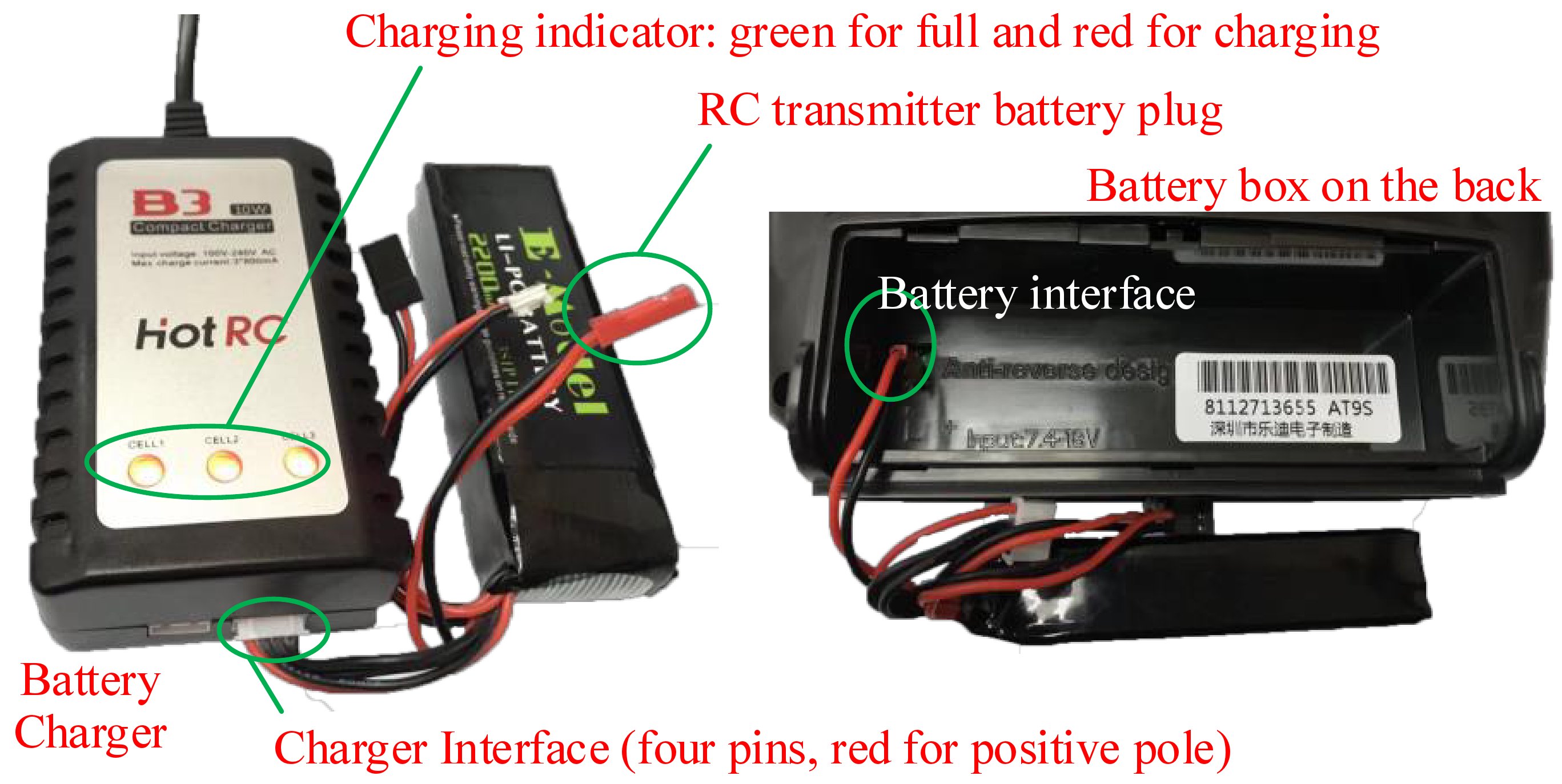
(1). Battery and charger instructions
The left side of Fig. 2.14 shows the battery and the charger. The battery begins to charge when the four-port charging head of the battery is inserted into the socket on the charger. Red and green indicator colors represent the “charging” and “fully charged” status, respectively. The RC transmitter battery is installed
 ../_images/Quan-ch2-Fig2.14.jpg
Fig. 2.14 RC transmitter, battery, and charger
../_images/Quan-ch2-Fig2.14.jpg
Fig. 2.14 RC transmitter, battery, and charger
(2). RC receiver initial setting
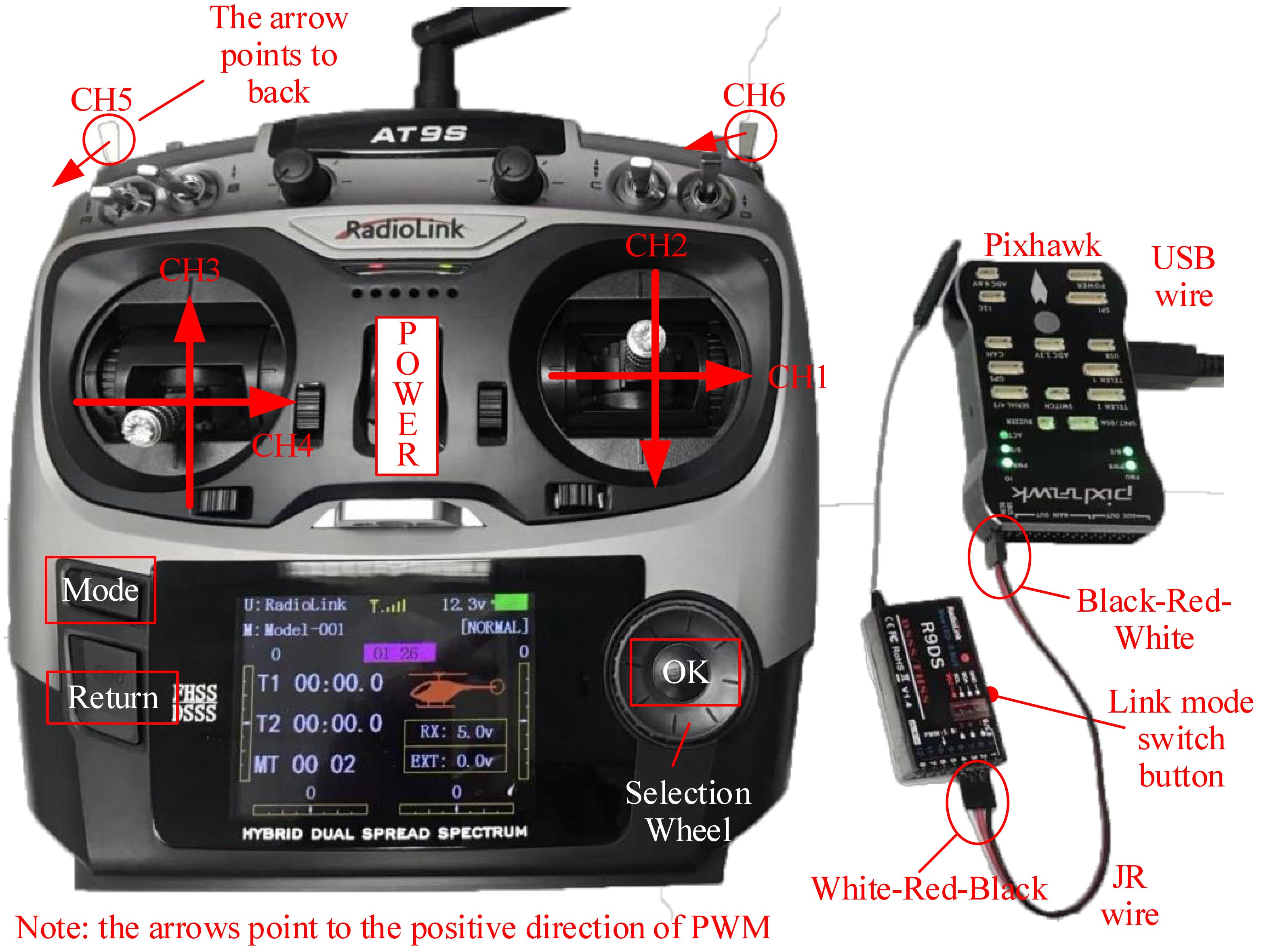
1). Connect the RC receiver and the Pixhawk according to Fig. 2.15. The horizontal pin on the downside of the tail face of the receiver must be connected to the left-most RC pin on the tail face of the Pixhawk with a three-line JR line, and the Pixhawk MicroUSB port must be connected to the computer USB Type-A interface to supply power to the receiver and the Pixhawk.
 ../_images/Quan-ch2-Fig2.15.jpg
Fig. 2.15 RC transmitter and receiver configuration
../_images/Quan-ch2-Fig2.15.jpg
Fig. 2.15 RC transmitter and receiver configuration
2). How to rematch the RC transmitter with an RC receiver (the connection has been completed by default, and this step needs to be performed only when problems occur in the connection of the receiver and the transmitter). Turn on the power of the RC transmitter (all other RC transmitters should be turned off), and correctly connect the receiver with the Pixhawk and the computer. Then, press the matching switch on the right side of the receiver with a pen tip or needle (see Fig. 2.15) for more than one second. At this time, the LED of the receiver starts to flash, which indicates that it is searching for the nearest RC transmitter. When the receiver LED flashes seven or eight times and then remains constant, it means that the matching process is finished and a connection has been successfully established between the RC transmitter and receiver.
3). S.BUS signal mode selection (the receiver is in this mode by default; thus, this step is typically not performed). The S.BUS mode allows the Pixhawk to transmit all channel PWM signals through one JR line. If the Pixhawk is powered up and connected to the receiver, the LED on the receiver is blue-white, which indicates that it is already in S.BUS mode and no setup is required. If the receiver LED is red, readers need to double-press (press twice within one second) the matching switch on the right side of the receiver. If the receiver LED turns blue-white, then the S.BUS mode has been successfully set.
(3). RC transmitter setting
1). Pull up the “POWER” switch shown in Fig. 2.15 to open the RC transmitter.
2). Setting the Language and Turning off the Sound
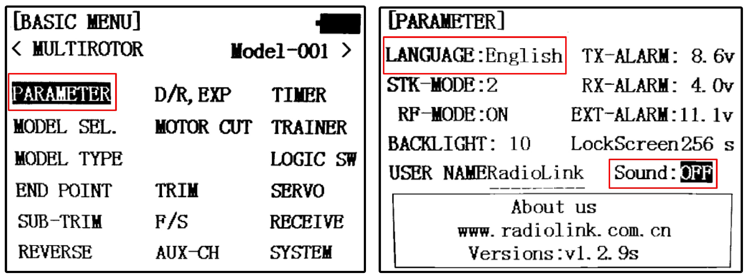
Press the “Mode” button on the RC transmitter shown in Fig. 2.15 for several seconds to enter the model setting page shown in Fig. 2.16. Roll the “Selection Wheel” on the RC transmitter shown in Fig. 2.15, move the cursor to “PARAMETER”, and press the “OK” button on the RC transmitter shown in Fig. 2.15 to enter the RC transmitter parameter setting page. Scroll the “Selection Wheel” to select the “English” item, click the “OK” button, and then scroll the “Direction Wheel” again to select the desired display language. Then click the “OK” button to confirm the selection. Because this experiment is mainly performed indoor, it is recommended to turn off the speakers of the RC transmitter to prevent disturbing people nearby. As shown in Fig. 2.16, modify the “Sound” option from “ON” to “OFF”.
 ../_images/Quan-ch2-Fig2.16.jpg
Fig. 2.16 RC transmitter parameter setting page
../_images/Quan-ch2-Fig2.16.jpg
Fig. 2.16 RC transmitter parameter setting page
3). Multicopter mode setting
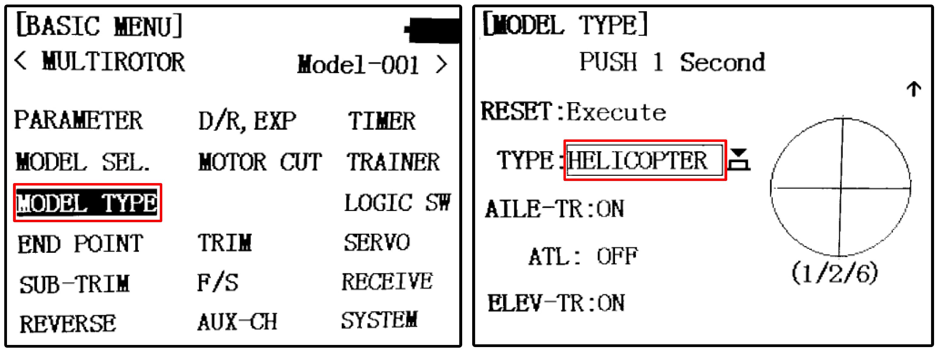
Press the “Mode” button for several seconds to enter the “BASIC MENU” page, and click the “MODEL TYPE” item to enter the model type selection page shown in Fig. 2.17.
Change the “TYPE” item from “HELICOPTER” to “MULTICOPTER”, and then press the “OK” button for several seconds to set the control mode to Multicopter.
 ../_images/Quan-ch2-Fig2.17.jpg
Fig. 2.17 Multicopter control mode switching of RC transmitter
../_images/Quan-ch2-Fig2.17.jpg
Fig. 2.17 Multicopter control mode switching of RC transmitter
4). Throttle channel reverse setting
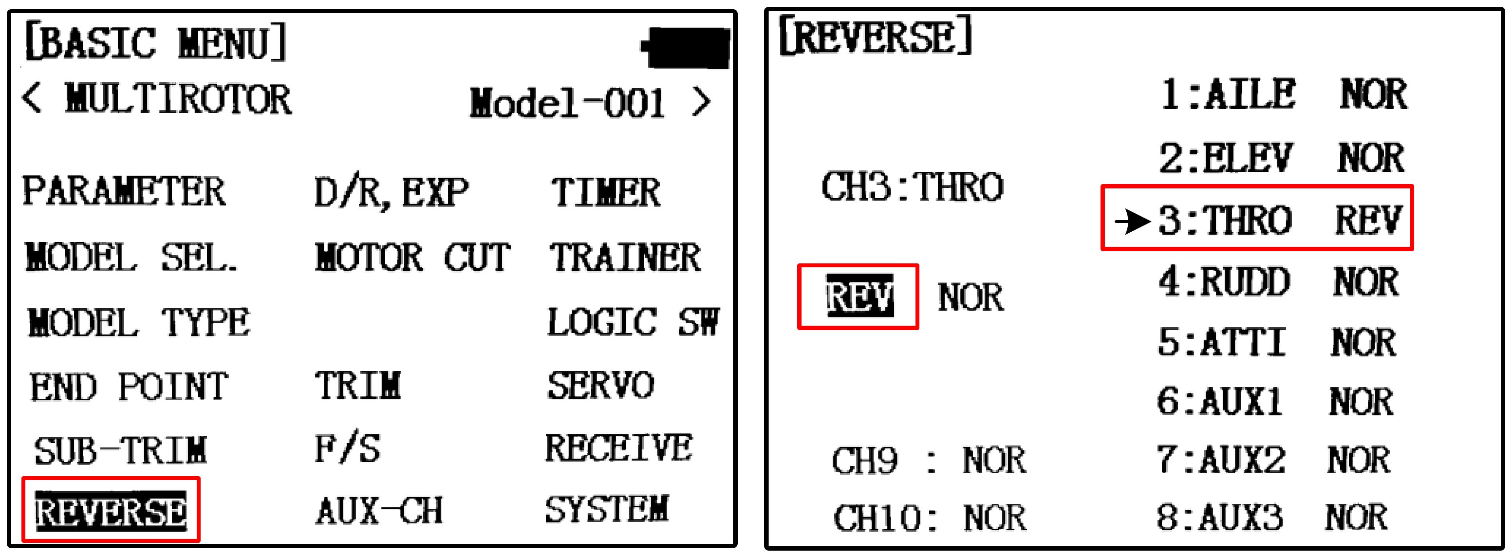
The throttle channel of the RadioLink transmitter is opposite to normal RC transmitters, and the throttle channel reverse needs to be set. Press the “Mode” button for several seconds to enter the “REVERSE” setting page shown in Fig. 2.18, and change the throttle channel from “NOR” to “REV”.
5). CH5-CH6 mode switching channel setting
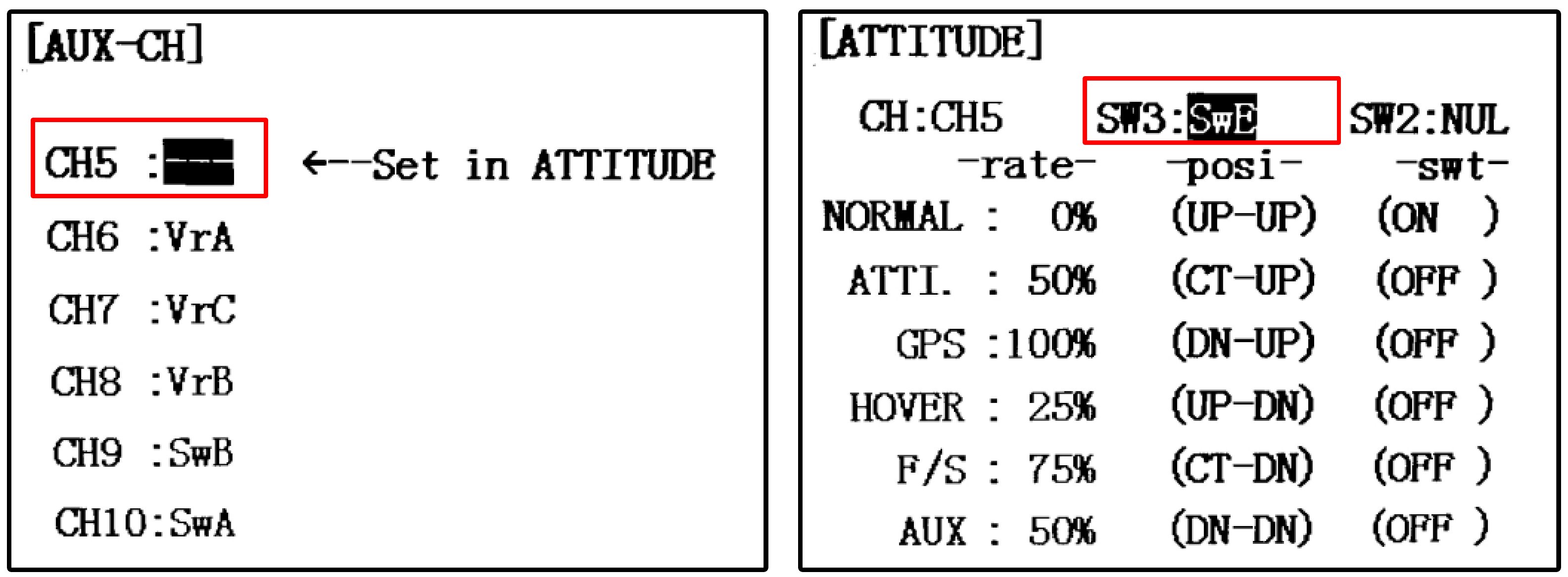
Because of experimental requirements, CH5 shown in Fig. 2.15 of the RC transmitter needs to be mapped to a three-position switch for mode switching of the Pixhawk. Press the “Mode” button for several seconds, and click the “AUX-CH” item next to the “REVERSE” item shown in Fig. 2.18.
As shown in Fig. 2.19, on the “AUX-CH” setting page, click the “CH5” item to enter the channel setting page, and map CH5 to a three-position switch “SwE” on the RC transmitter (switch “E” is located in the top-left corner of the RC transmitter in Fig. 2.15).
Similarly, the “CH6” item in Fig. 2.19 must be modified to a three-position switch “SwG” of the RC transmitter (switch “G” is located in the upperright corner of the RC transmitter in Fig. 2.15).
 ../_images/Quan-ch2-Fig2.18.jpg
Fig. 2.18 Throttle channel reverse setting
../_images/Quan-ch2-Fig2.18.jpg
Fig. 2.18 Throttle channel reverse setting
 ../_images/Quan-ch2-Fig2.19.jpg
Fig. 2.19 CH5-CH6 mode switching channel setting
../_images/Quan-ch2-Fig2.19.jpg
Fig. 2.19 CH5-CH6 mode switching channel setting
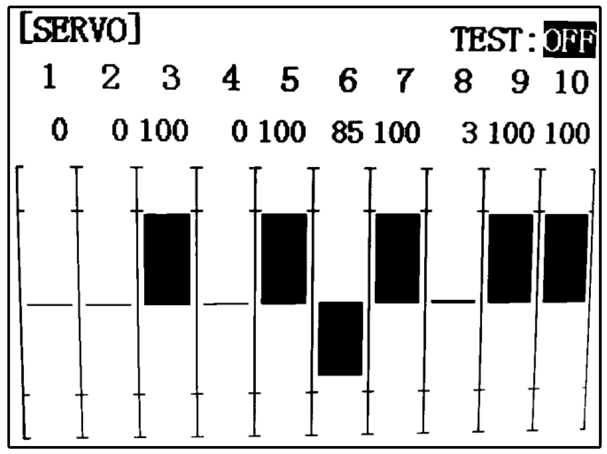
6). Channel confirmation
Restart the RC transmitter, and press the “Return” button (see Fig. 2.15) on the RC transmitter to enter the “SERVO” page (see Fig. 2.20). In this page, the PWM value of each channel can be verified by moving sticks and switches on the RC transmitter. Note that, as shown in Fig. 2.20, the channel value reaches an upper limit of 100 corresponding to the desired PWM value of 1100 µs; the channel value reaches the lower limit 100, corresponding to the desired output PWM value of 1900 µs. Note that the actual PWM value range received by the RC receiver may not equal to 1100–1900 due to various errors. So RC calibration is important for autopilots to correctly recognize the control commands from the ground pilot. For example, in Fig. 2.20, the third channel is located at an upper limit of 100, which indicates that the PWM value is about 1100 µs; the other three channels are located at 0 positions, which indicates that the corresponding PWM value is about 1500 µs.
It is important to understand the correct relationship between the stick position and the PWM value of each channel. Move each channel stick in Fig. 2.15 to confirm that each channel corresponds correctly to the following rules.
CH1: this corresponds to the horizontal movement of the right-hand stick of the RC transmitter. The right-hand stick moves from left to right, corresponding to a PWM value that changes from 1100 to 1900. CH2: this corresponds to the vertical movement of the right-hand stick of the RC transmitter. The right-hand stick moves from top to bottom, corresponding to a PWM value that changes from 1100 to 1900. CH3: this corresponds to the vertical movement of the left-hand stick of the RC transmitter. The left-hand stick moves from top to bottom, corresponding to a PWM value that changes from 1900 to 1100 (opposite to CH2). CH4: this corresponds to the horizontal movement of the left-hand stick of the RC transmitter. The left-hand stick moves from left to right, corresponding to a PWM value that changes from 1100 to 1900. CH5: this corresponds to the three-position switch on the upper-left side of the RC transmitter. The switch moves from the top position (the farthest position from the user), middle position, and bottom position (the closest position from the user), corresponding to PWM values of 1100, 1500, and 1900, respectively. CH6: this corresponds to the three-position switch on the upper-right side of the RC transmitter. The switch moves to the top position (the farthest position from the user), middle position, and bottom position (the closest position from the user), corresponding PWM values of 1100, 1500, and 1900, respectively.
 ../_images/Quan-ch2-Fig2.20.jpg
Fig. 2.20 RC transmitter stick position and direction
../_images/Quan-ch2-Fig2.20.jpg
Fig. 2.20 RC transmitter stick position and direction
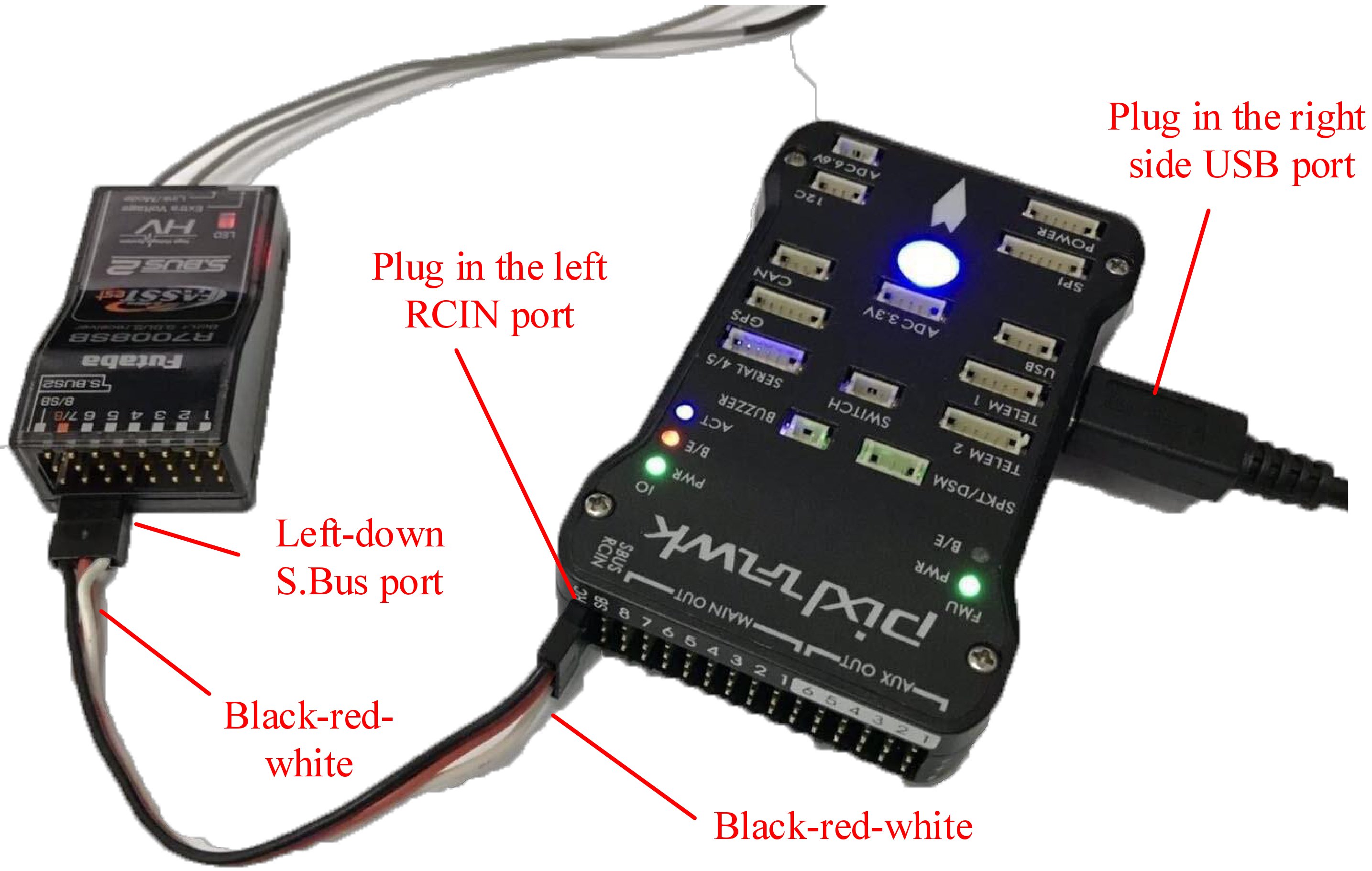
3.1.2. Configuration for Futaba T14SG The connection between the Futaba receiver and the Pixhawk autopilot is slightly different from that of the RadioLink receiver. The specific connection is shown in Fig. 2.21. In the following paragraphs, the setup process for the Futaba RC transmitter is introduced.
 ../_images/Quan-ch2-Fig2.21.jpg
Fig. 2.21 Pixhawk and Futaba receiver connection diagram
../_images/Quan-ch2-Fig2.21.jpg
Fig. 2.21 Pixhawk and Futaba receiver connection diagram
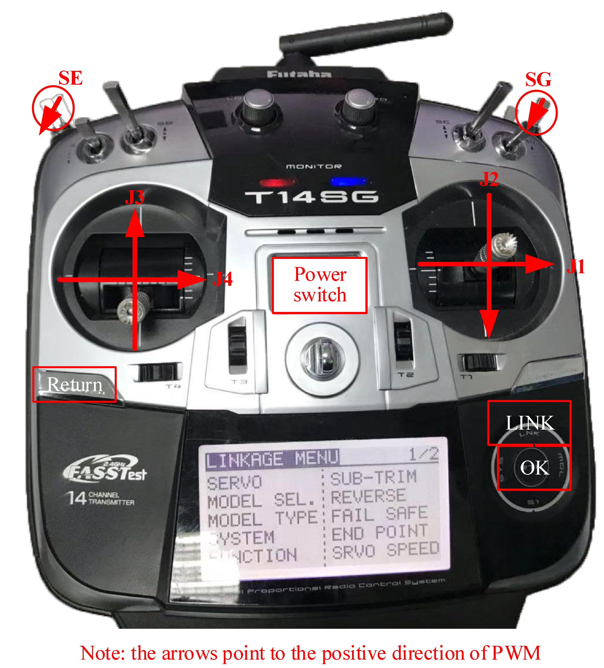
As shown in Fig. 2.22, the Futaba T14SG RC transmitter needs to use six channels: the J1 stick (CH1, roll channel), J2 stick (CH2, pitch channel), J3 stick (CH3, throttle channel), J4 stick (CH4, yaw channel), SE three-position switch (upper-left switch, CH5 mode channel), and SG three-position switch (upper-right switch, CH6 mode channel). The basic process of setting the Futaba T14SG RC transmitter is summarized as follows.
 ../_images/Quan-ch2-Fig2.22.jpg
Fig. 2.22 Futaba T14SG RC transmitter
../_images/Quan-ch2-Fig2.22.jpg
Fig. 2.22 Futaba T14SG RC transmitter
(1). Double-click the “LINK” button on the RC transmitter in Fig. 2.22 to enter the “LINKAGE MENU” link setting page. As shown in Fig. 2.23a, enter the “MODEL TYPE” page and change the “TYPE” to “MULTICOPTER”;
(2). Go back to the “LINKAGE MENU” page, and enter the “FUNCTION” page to confirm the channel mapping is the same as that shown in Fig. 2.23b, wherein the first to fourth channels of the RC transmitter correspond to the J1–J4 sticks;
(3). Go back to the “LINKAGE MENU” page, and enter the “REVERSE” page to confirm that the reverse direction of the channel is as shown in Fig. 2.23c, i.e., only the third channel (throttle) is reversed;
(4). Go back to the “LINKAGE MENU” page, and enter the “FUNCTION”, and scroll to the second page for the setting of CH5 to CH8. As shown in Fig. 2.23d, set the “CTRL” option of the “5 MODE” channel to “SE” stick (the upper-left stick of the RC transmitter).
(5). As in the previous step, set the “6 AUX1” channel shown in Fig. 2.23d to the “SG” stick (the upper-right stick of the RC transmitter).
After the above settings, similar to the RadioLink AT9S in Fig. 2.20, it is also necessary to verify that the PWM output of each stick follows the correct definition required by this book.
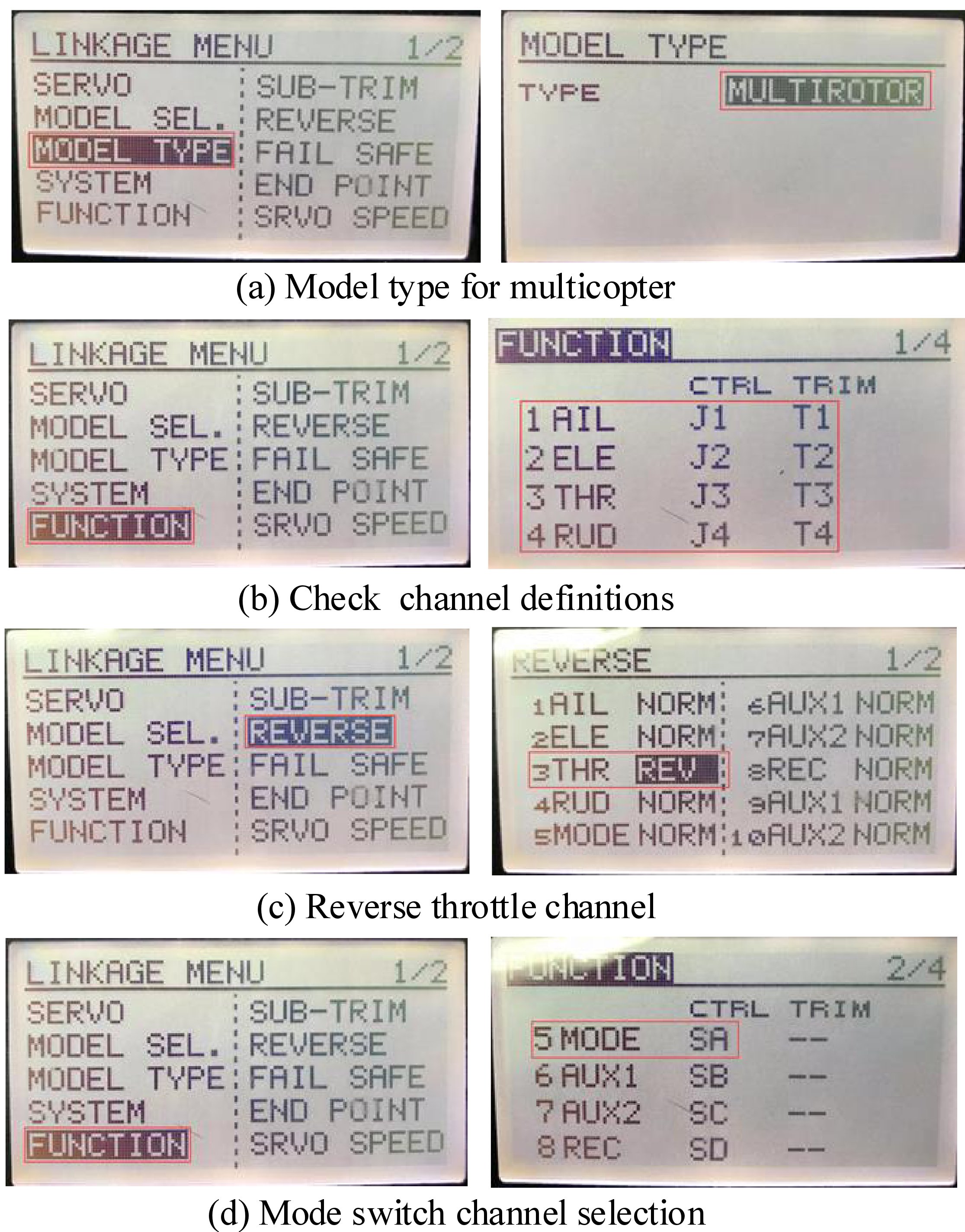 ../_images/Quan-ch2-Fig2.23.jpg
Fig. 2.23 Futaba T14SG RC transmitter
../_images/Quan-ch2-Fig2.23.jpg
Fig. 2.23 Futaba T14SG RC transmitter
3.2. Pixhawk Autopilot System Configuration
Several basic firmware uploading and 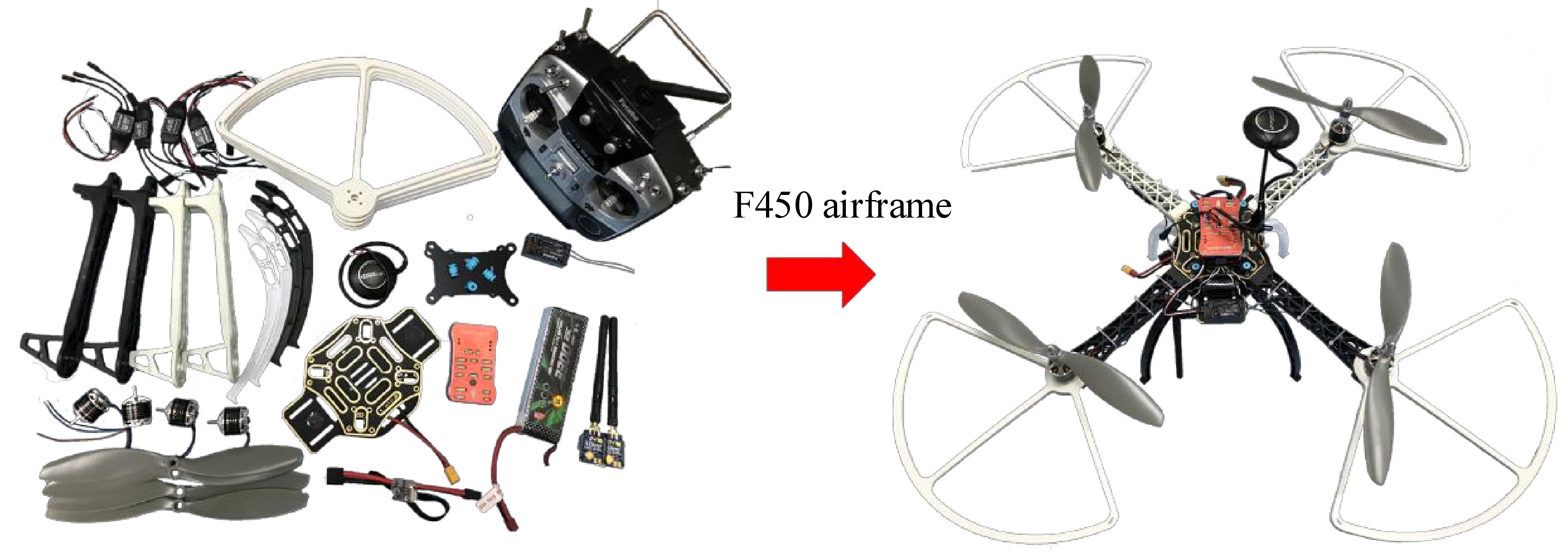 configuration operations are required for the brand-new Pixhawk to ensure that the Pixhawk autopilot meets the experimental requirements and ensure that the operation and configuration of Pixhawk are correct. The configuration method is summarized below.
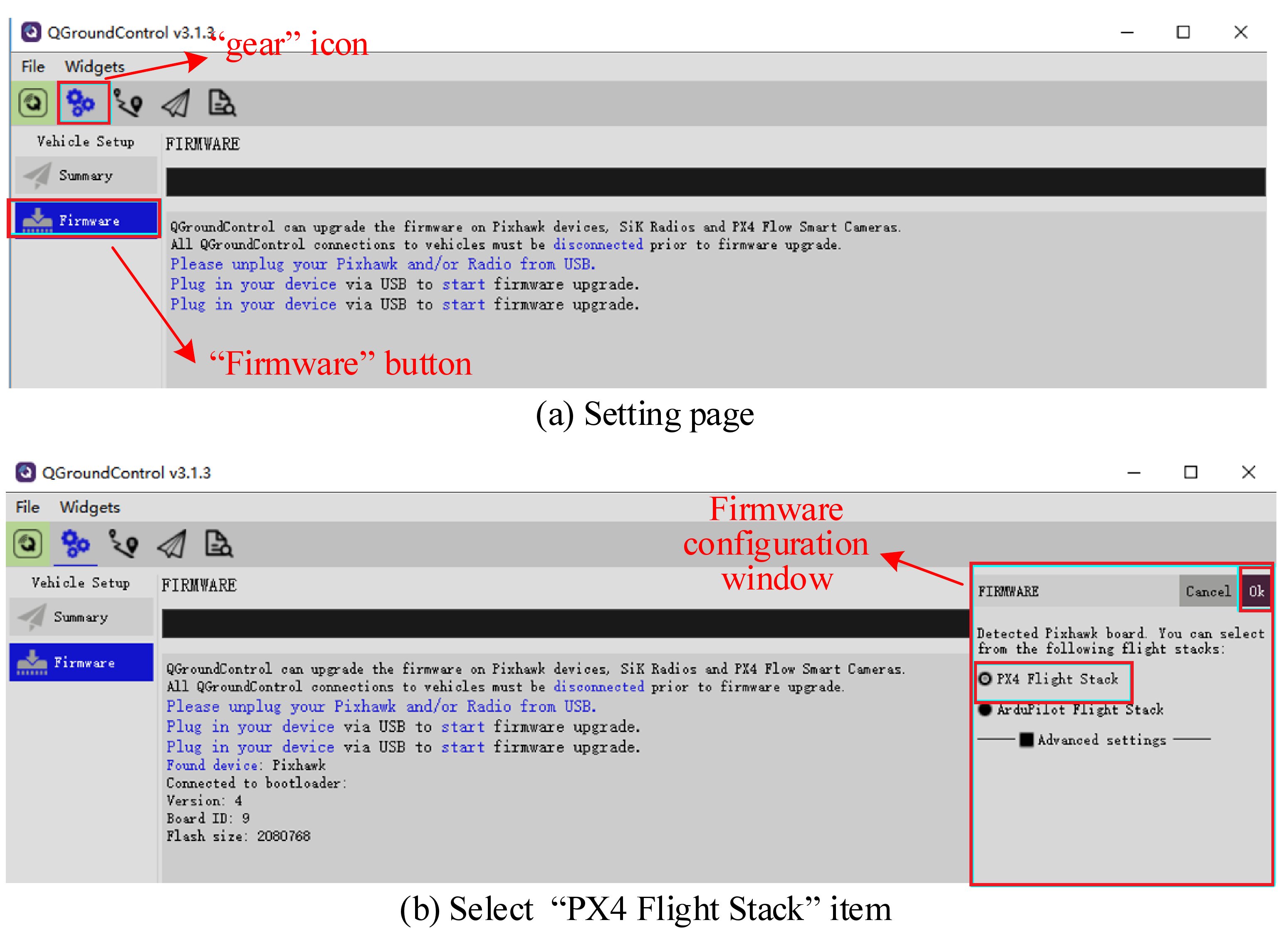
(1). Open the QGC software.
(2). As shown in Fig. 2.24a, click the “gear” icon to enter the setting page; then, click the “Firmware” button to enter the firmware burning page.
(3). Connect the Pixhawk autopilot and the computer using a USB cable. At this time, the software will automatically recognize the Pixhawk hardware. As shown in Fig. 2.24b, a firmware configuration window will pop up on the right side of the UI. Select the “PX4 Flight Stack” item, and click “OK”; then, QGC begins to automatically download (see Fig. 2.24 if the computer is not connected to the Internet) and burn the latest PX4 firmware into the Pixhawk autopilot hardware.
 ../_images/Quan-ch2-Fig2.24.jpg
Fig. 2.24 Pixhawk autopilot configuration on QGC
../_images/Quan-ch2-Fig2.24.jpg
Fig. 2.24 Pixhawk autopilot configuration on QGC
(4). After the firmware is burned, the Pixhawk will automatically restart and reconnect to the QGC software. Then, as shown in Fig. 2.25, enter the “Airframe” tab, select “HIL Quadcopter X” airframe type , and click the “Apply and Restart” button. Then the autopilot will automatically restart to finish the configuration for HIL simulation.
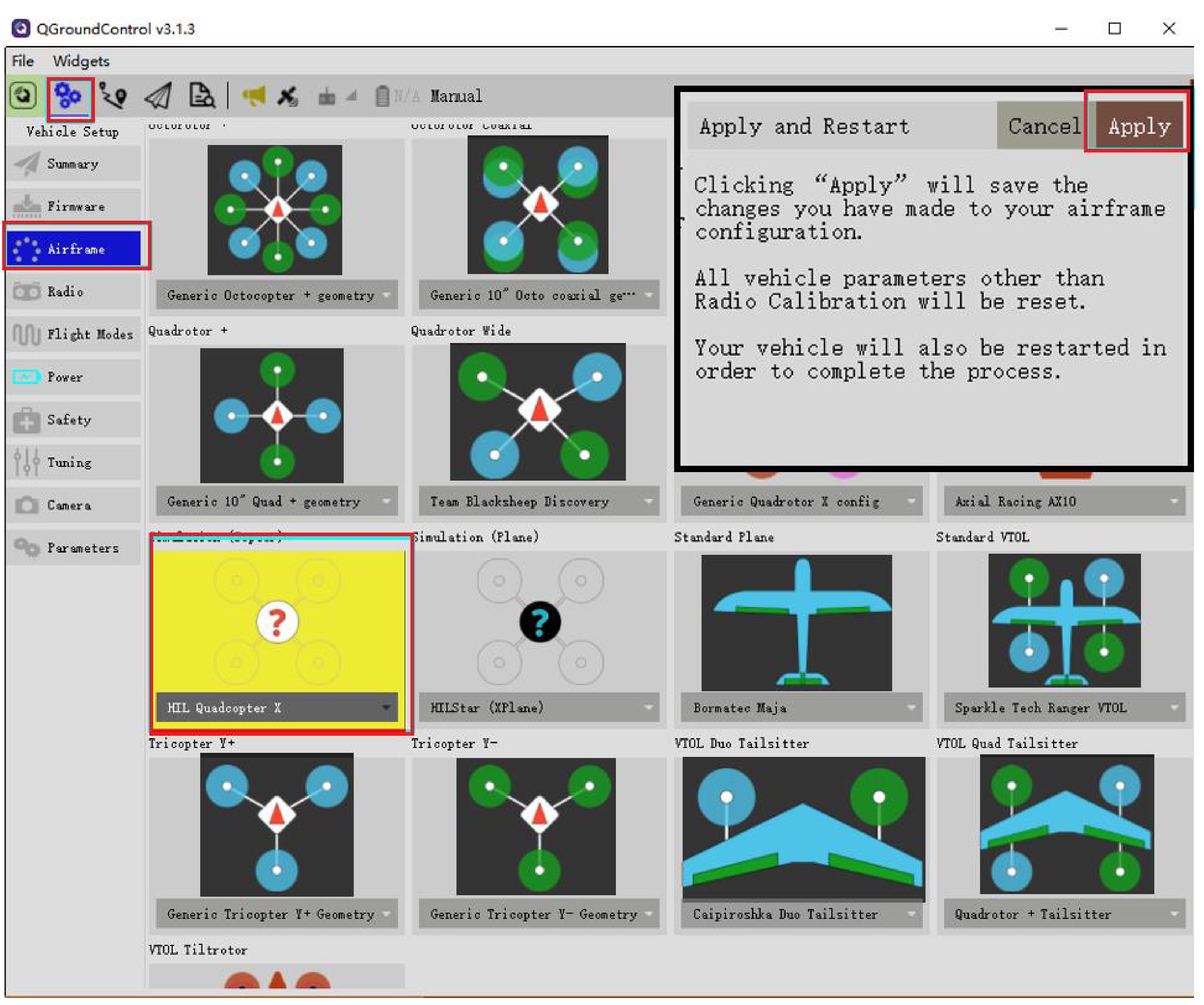 ../_images/Quan-ch2-Fig2.25.jpg
Fig. 2.25 Selecting “HIL Quadcopter X” airframe type
../_images/Quan-ch2-Fig2.25.jpg
Fig. 2.25 Selecting “HIL Quadcopter X” airframe type
(5). After rebooting, QGC will automatically reconnect to Pixhawk. Check each configuration page to ensure that the Pixhawk autopilot has been in the HIL simulation mode and that no warnings appear.
3.3. Airframe and Propulsion System Configuration
The parameters of the multicopter simulation model in both SIL and HIL simulations are from a quadcopter with a diagonal size (opposite motor axis distance) of 450 mm and a weight of 1.4 kg. For the subsequent flight experiments, it is necessary to ensure that the configuration of the multicopter is as close as possible to the simulation model. The experiments presented in this book select the most popular F450 multicopter (see Fig. 2.26) with the following configuration.
(1). Airframe : DJI Flame Wheel F450 airframe
Airframe weight (fuselage + arm + landing gear): 282 g Protection airframe: weight: 4×32 g Diagonal size: 450 mm Take-off weight: within the range 800–1600 g Recommended propeller: 8–10inches (2). Propulsion system : DJI E310 propulsion suite (four motors, four ESCs, and four propellers)
Motor size: 23×12 mm, KV value: 960 RPM/V, weight: 60 g Propeller size: 24×12.7 cm (9.4×5.0in), weight: 13 g ESC size: 74×32×10 mm, maximum continuous current: 20 A, weight: 43 g (3). Battery : GENS ACE LiPo battery
Capacity: 4000 mAh Voltage: 3S (11.1 V) Discharge rate: 25C Weight: 300 g (4). Autopilot : Pixhawk 1 (2MB flash version)
-
Compiling command: px4fmu-v3_default, size: 81×47×16 mm, weight: 36 g
-
GPS module: UBlox NEO-M8N GPS, module weight: 14 g, weight: 24 g
-
Other accessories: power module, buzzer, safety switch, connector, and antivibration damper weighing a total of 60 g
../_images/Quan-ch2-Fig2.26.jpg
Fig. 2.26 F450 airframe and its components
After completing the assembly of the aerial vehicle, readers can follow the PX4 official website tutorial19 to conduct preliminary flight tests to ensure that all functions are normal.
If you have any question, please go to https://flyeval.com/course for your information.