drone history
open source projects
| Table 1.3 Major open source projects |
|---|
| Open source projects Web site |
| Ardupilot http://ardupilot.com |
| Openpilot http://www.openpilot.org |
| Paparazzi http://paparazziuav.org |
| Pixhawk https://pixhawk.ethz.ch |
| Mikrokopter http://www.mikrokopter.de |
| KKmulticopter http://www.kkmulticopter.kr |
| Multiwii http://www.multiwii.com |
| Aeroquad http://www.aeroquadstore.com |
| Crazyfliehttps://www.bitcraze.io/category/crazyflie |
| CrazePony http://www.crazepony.com |
| DR. R&D http://www.etootle.com |
| ANO http://www.anotc.com |
| Autoquad http://autoquad.org |
| MegaPirate http://megapiratex.com/index.php |
| Erlerobot http://erlerobotics.com |
| MegaPirateNG http://code.google.com/p/megapirateng |
| Taulabs http://forum.taulabs.org |
| Flexbot http://www.flexbot.cc |
| Dronecode (Operating System) https://www.dronecode.org |
| Parrot API (SDK)https://projects.ardrone.org/embedded/ardrone-api/index.html |
| 3DR DRONEKIT (SDK) http://www.dronekit.io |
| DJI DEVELOPER (SDK) http://dev.dji.com/cn |
| DJI MATRICE 100+ DJI Guidance https://developer.dji.com/cn/matrice-100 SDKforXMission (SDK) http://www.xaircraft.cn/en/xmission/developer |
| Ehang GHOST (SDK) http://dev.ehang.com |
chapter overview
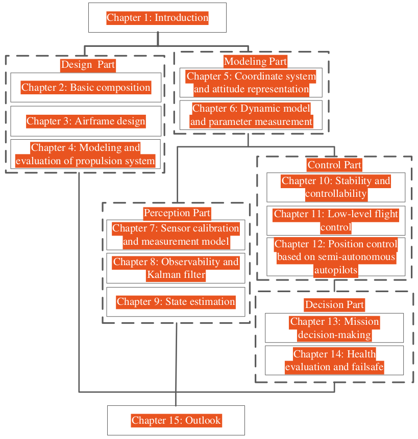
This book has five parts, fifteen chapters, as shown in Fig. 1.20.
- Chapter 1. Introduction. It includes the basic conceptions, remote control and performance eval-
uation of a multicopter, history of technology development of multicopters, and the objective and
structure of this book.
(1) Part I. Design Part
Through this part, readers can have a deeper understanding about the composition of a multicopter system, the configuration and structural design for the airframe, and the choice of
the propulsion system. These correspond to Chaps. 2–4, respectively. - Chapter 2. Basic composition. This chapter includes three parts: the airframe, the propulsion system, and the command and control system. In the aspects of the function and key parameters, the fuselage, landing gear, duct, motor, ESC, propeller, battery, RC transmitter and receiver, autopilot, GCS, and radio telemetry are introduced.
- Chapter 3. Airframe design. This chapter introduces the basic configuration and the brief consider- ation on how to attenuate vibration and to reduce the noise.
- Chapter 4. Modeling and evaluation of propulsion system. The propulsion system of a multicopter
consists of propellers, motors, ESCs, and batteries. The components are modeled with respect to
energy. Then, based on these, the flight performance, such as the maximum flight time in hover mode
and the maximum payload, is evaluated.
(2) Part II. Modeling Part
Through this part, readers can have a deeper understanding about the dynamic model of a multicopter, which will be further used for the state estimation and control. This part contains two chapters, including the coordinate system, attitude representation, dynamic model, and parameter measurement.
- Chapter 5. Coordinate system and attitude representation. First, this chapter introduces the Earth- Fixed Coordinate Frame (EFCF) and Aircraft-Body Coordinate Frame (ABCF). Then, the attitude is represented in the form of three types: Euler angle, rotation matrix, and quaternion. This chapter is the basis for Chap. 6.
- Chapter 6. Dynamic model and parameter measurement. First, the multicopter control model is
introduced, which includes rigid body kinematics, rigid body dynamics, the control
effectiveness model, and the propulsor model. Secondly, the aerodynamic drag model is further introduced, which will be used for the state estimation in Chap. 9. Finally, methods are proposed to identify the parameters of a multicopter model.(3) Part III. Perception Part
Through this part, readers can have a deeper understanding about the state estimation of a multicopter, which will be further used for control. This part contains three chapters.
- Chapter 7. Sensor calibration and measurement model. A multicopter is equipped with many sen- sors, such as the three-axis accelerometer, three-axis gyroscope, three-axis magnetometer, barometer, ultrasonic range finder, laser range finder, GPS receiver, and camera. Low-cost inertial sensors have bias, misalignment angles, and scale factors, which are not negligible and differ from one multicopter sensor board to another. If the sensors are not calibrated, then the position and attitude estimation are inaccurate before takeoff. This may cause flight accidents. In this chapter, the calibration methods are introduced first. Then, the measurement models of sensors are given.
- Chapter 8. Observability and Kalman filter. In fact, with related sensors, there still exists a question whether the state information can be estimated in theory, that is, the observability problem. If the system is unobservable, then it makes no sense to design filters. After introducing the observability, a widely used filter, namely Kalman filter, is introduced in detail.
- Chapter 9. State estimation. Sensors have noise and redundancy. Moreover, some states cannot be
obtained from sensors directly. Therefore, multisensor data fusion is very important. This chapter
will contain the attitude estimation, position estimation, velocity estimation, and obstacle
estimation.
(4) Part IV. Control Part
Through this part, readers can have a deeper understanding about control of a multicopter, where the methods introduced are commonly used. There are three chapters in this part.
- Chapter 10. Stability and controllability. Before controller design, the stability of a multicopter is defined and some simple stability criteria are given. Secondly, the controllability of a multicopter is also introduced. Without it, all fault-tolerant control methods are inapplicable. An interesting example of controllability analysis for hexacopter propulsor degradation and failure will be given. Controllability can be also used to evaluate the design of a multicopter or health of a multicopter.
- Chapter 11. Low-level flight control. This chapter will introduce how to design a motor controller that drives a multicopter to fly to a desired position. The process includes the position control, attitude control, control allocation, and motor control. The methods for position control and attitude control are based on both the linear model and the nonlinear model.
- Chapter 12. Position control based on Semi-Autonomous Autopilots (SAAs). In this chapter, the SAA
will be considered as a “black box.” This will be very helpful in the secondary development. Not
only has it avoided the trouble of modifying the low-level source code of autopilots, but also can
it utilize commercial reliable autopilots to achieve the targets. This simplifies the whole design.
This chapter will introduce the system identification and controller design process.
(5) Part V. Decision Part
Through this part, readers can have a deeper understanding about high-level decision-making of a multicopter. Decision-making has two objectives: mission decision-making and failsafe,¹² which cor- responds to Chaps. 13 and 14, respectively.
- Chapter 13. Mission decision-making. For FAC, it consists of the task planning and path planning, where the former informs the multicopter where to go next and latter informs the multicopter how to go there step by step. In the path planning, two problems considered are how to follow a straight-line path and how to avoid an obstacle. For SAC, a switching logic between the autonomous hover and the remote control will be introduced.
- Chapter 14. Health evaluation and failsafe. For civil applications, safety is often more important than fulfilling tasks. During a flight, the communication failure, sensor failure, and propulsion system failure all may happen. These accidents may ruin tasks. In this case, it is important to decide on the next action of multicopters. In this chapter, some failure problems are introduced first. Then, some methods of health evaluation are given. Moreover, failsafe suggestions are listed as well. Finally, a failsafe mechanism as a case is designed by using the Extended Finite State Machine (EFSM).
- Chapter 15. Outlook. This chapter summarizes the potential technologies which will propel the
development of multicopters in the first place. Secondly, innovation trends are
proposed. Thirdly, potential risks are further analyzed. Finally, it provides the personal thoughts about the opportunities and challenges. The structure shown in Fig. 1.20 has considered three types of readers. Readers who
are only interested in design can read this chapter, Design Part, and Chap. 15. Readers who are only interested in perception can read the this chapter, Modeling Part, Perception Part, and Chap.- Readers who are only interested in control are suggested to read this chapter,
Modeling Part,Control Part,Decision Part, and `Chap. 15’.
- Readers who are only interested in control are suggested to read this chapter,
chapter 1
diagonal size
Diagonal size is the diameter (usually in mm) of the circumcircle determined by the motor axes. In general, as shown in Fig. 2.5, it is the distance of motor axes in the diagonal line and it is used to indicate the size of an airframe. The diagonal size restricts the size of propeller, which determines the maximum thrust and then the payload capacity.
duct
In addition to protecting the blade and ensuring personal safety, the duct can also enhance the efficiency of thrust and reduce noise. The thrust of a multicopter with ducts is composed of two parts, i.e., the thrust of the propeller and the additional thrust induced by the duct, as shown in Fig. 2.7.

propulsion system
propeller
Generally, the propeller model is described by a four-digit number, such as a 1045 (or 10 × 45) propeller, among which the first two represents the diameter of the propeller (unit: inch), and the latter two represents the propeller pitch (also referred to as screw pitch, blade pitch or simplified as pitch, unit: inch). Therefore, the APC1045 propeller implies that the propeller belongs to APC series, and the diameter and pitch of the propeller is 10 in. and 4.5 in., respectively.
- chord length
- moment of inertia


- propeller specific thrust
M power(W) = Torque(N.m) X Propeller speed (rad/s)
- size
- KV value for motors
- No-load current, voltage
- max current/power
- resistance
- motor efficiency
Electronic speed controller

- maximum continuous/peak current
- voltage range
- resistance
- refresh rate
- programmability The performance of ESCs can be optimized by tuning internal parameters. There are three ways to set the parameters of ESCs, i.e., programmable cards as shown in Fig. 2.17, computer software via the USB, and RC transmitters. The parameters that can be set up include: throttle range calibration, low voltage protection, power outage value, current limitation, brakes mode, throttle control mode, switch timing setting, starting mode, and PWM mode setting.
- compatability
battery
- connection
- capacity
- discharge rate Discharge Rate (unit: C) = Current of Discharge (unit: mA) / Capacity (unit: mAh)
- resistance
- energy density
Energy density is the amount of energy stored in a given system or region of space per unit volume or mass, and the latter is more accurately termed specific energy. In general, the units for energy density and specific energy are (Watt × hour)/kg and (Watt × hour)/L, i.e., Wh/kg and Wh/L, respectively. Batteries with higher energy density are more popular due to the contradiction between volume (weight) and endurance for a product. Lithium-ion battery as a kind of clean energy is getting more and more attentions and is widely used in many applications. The energy density of Lithium-ion batteries varies from chemistry to chemistry and the energy density can range from 240 to 300 Wh/L (double of the NiCd, 1.5 times of NiMH).

command and control system
- frequency
- modulation
- channels
- mode
- throttle
- remote control distance
Autopilot
{# nothing on index to avoid visible raw text #}